
Find the approximate axial forces, shears, and moments for the all members of the frames using cantilever method.
Explanation of Solution
Given information:
The axial force acting at point M
The axial force acting at point I
The axial force acting at point E
The vertical distance of the member JM and KL
The vertical distance of the member EI, FJ, GK, and HL
The vertical distance of the member AE, BF, CG, and DH
The horizontal distance of the members AB, EF, and IJ
The horizontal distance of the members BC, FG, and JK
The horizontal distance of the members CD, GH, and KL
Take the counterclockwise moment is positive and clockwise moment is negative.
The axial force in horizontal direction, towards right is positive and towards left side is negative.
The axial force in vertical direction, towards upward is positive and towards downward is negative.
Calculation:
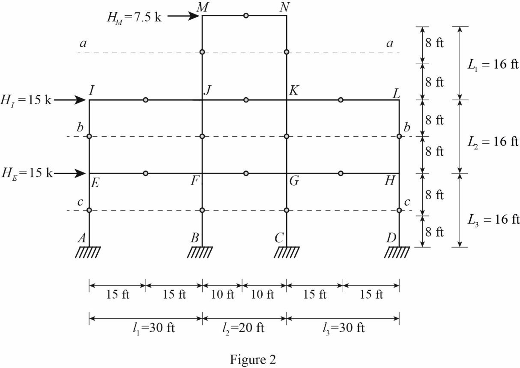
Insert the internal hinges at the midpoints of all the members of the given frame to obtain the simplified frame for approximate analysis.
Draw the simplified frame as in Figure (1).

For the calculation of column axial forces of story of the frame, pass an imaginary section aa through the internal hinges at the midheights of columns JM and KN, pass an imaginary section bb through the internal hinges at the midheights of columns EI, FJ, GK, and HL, and pass an imaginary section cc through the internal hinges at the midheights of columns AE, BF, CG, and DH.
Draw the free body diagram of the frame portion with the passed imaginary lines as in Figure (2).
Column axial forces:
Above section aa:
Draw the free body diagram of the frame portion above the section aa as in Figure (3).
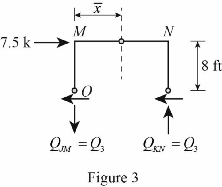
Determine the location of the centroid from support A using the relation.
Here, A is the area of the column sections,
Substitute 0 ft for
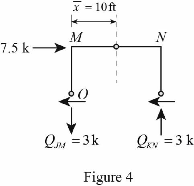
The location of the centroid from the column member JM is 10 ft.
The given lateral load is acting on the frame to the right, therefore the axial force in column JM located to the left of the centroid, must be tensile whereas the axial force in column KN placed to the right of the centroid, must be compressive.
Determine the axial force in the column members JM and KN using equilibrium conditions.
Take moment about point O.
Substitute 20 ft for
The axial force in the column members JM and KN is
Draw the free body diagram of the frame portion above the section aa with the axial forces in the column members as in Figure (4).
Draw the free body diagram of the frame portion above the section bb as in Figure (5).
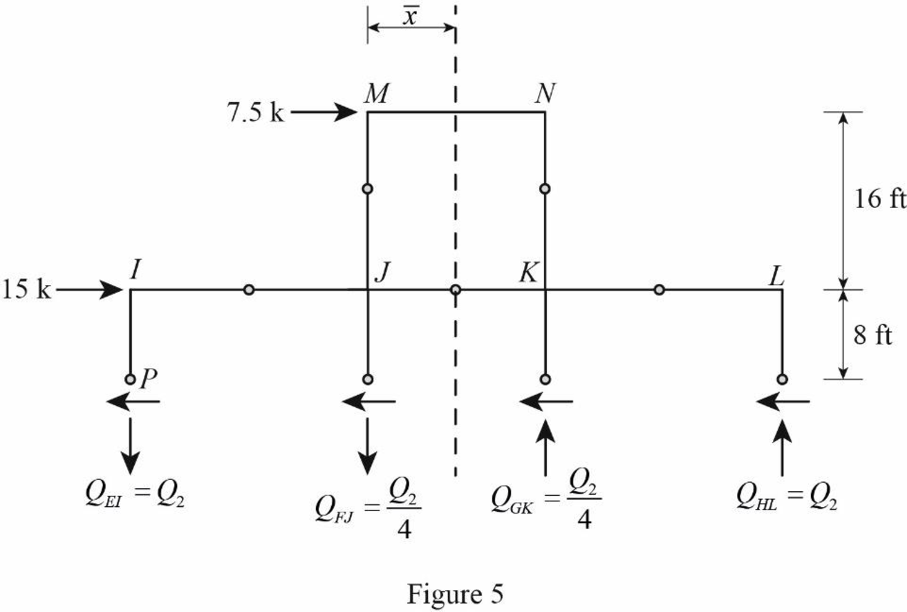
Consider the axial forces in the columns are to be linearly proportional to their distances from centroid.
The given lateral load is acting on the frame to the right, therefore the axial force in column EI and FJ located to the left of the centroid, must be tensile whereas the axial force in column GK and HL placed to the right of the centroid, must be compressive.
Refer Figure (5).
Determine the relationship in column axial force between the member EI and FJ using the relation.
Substitute 40 ft for
Determine the relationship in column axial force between the member EI and GK using the relation.
Substitute 30 ft for
Determine the axial force in the column members EI, FJ, GK, and HL using equilibrium conditions.
Take moment about point P.
Substitute
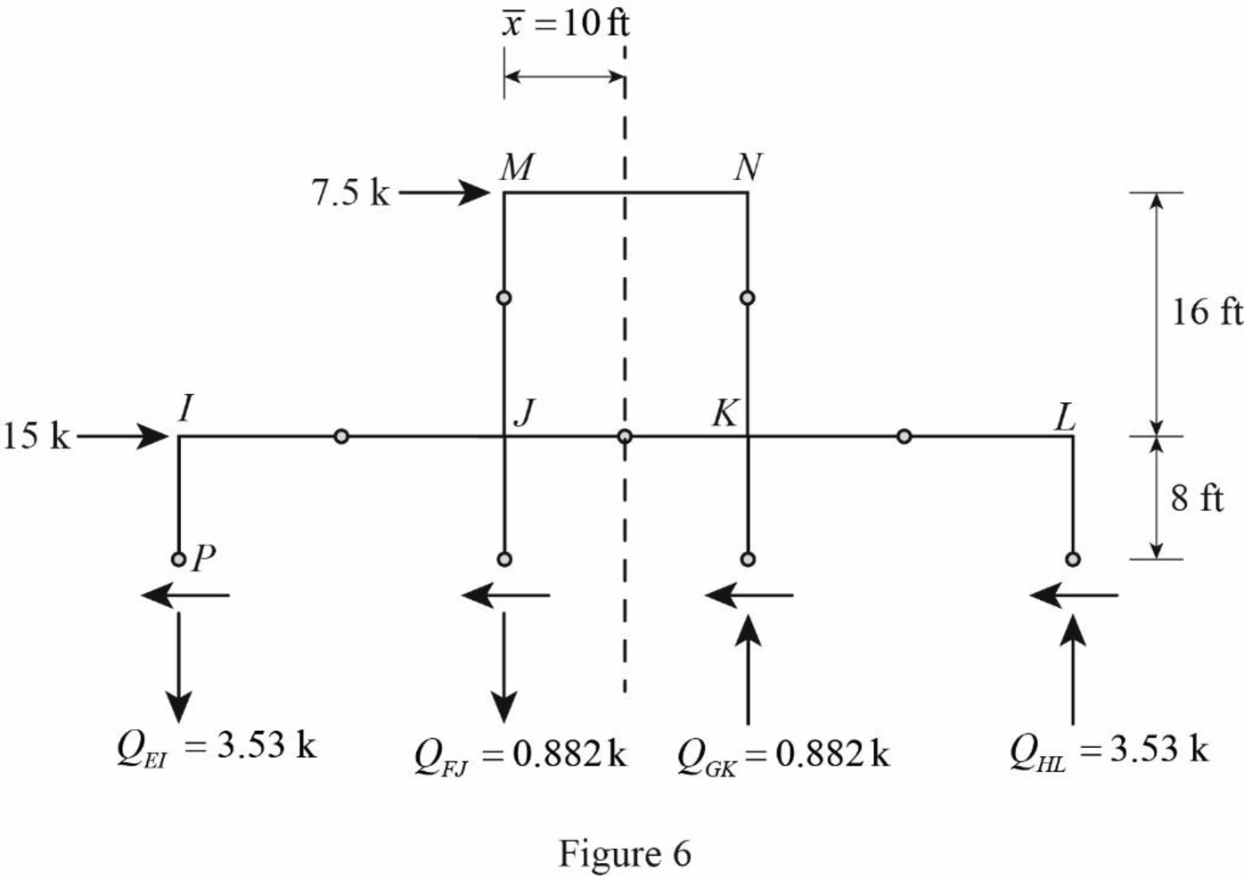
Determine the axial force in the column members FJ.
Substitute 3.53 k for
Determine the axial force in the column members GK.
Substitute 3.53 k for
Determine the axial force in the column members HL.
Substitute 3.53 k for
Draw the free body diagram of the frame portion above the section bb with the axial forces in the column members as in Figure (6).
Draw the free body diagram of the frame portion above the section cc as in Figure (7).
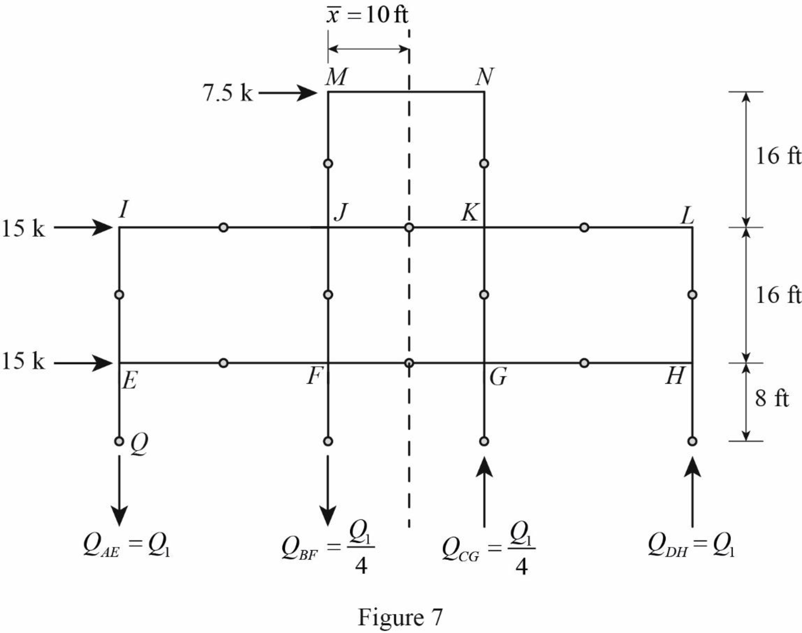
The given lateral load is acting on the frame to the right, therefore the axial force in column AE and BF located to the left of the centroid, must be tensile, whereas the axial force in column CG and DH placed to the right of the centroid, must be compressive.
Determine the relationship in column axial force between the member AE and BF using the relation.
Substitute 40 ft for
Determine the relationship in column axial force between the member AE and CG using the relation.
Substitute 30 ft for
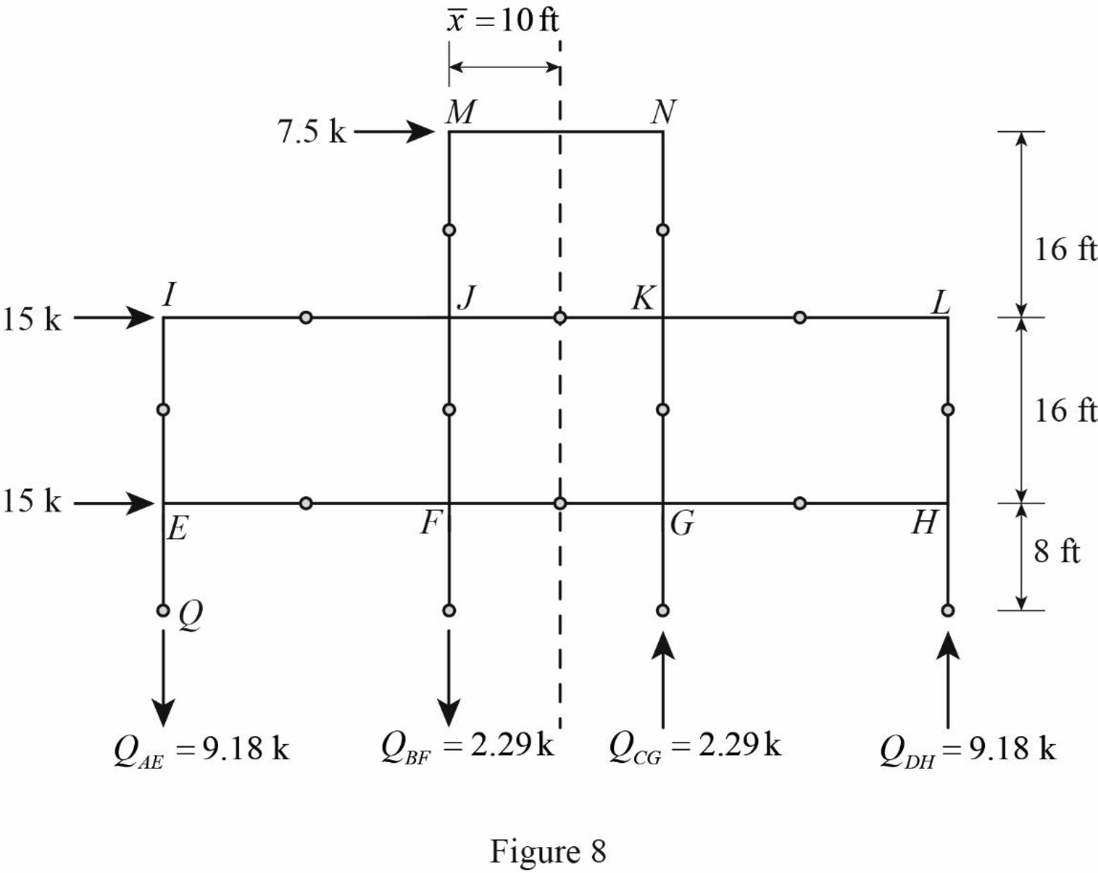
Determine the axial force in the column members AE, BF, CG, and DH using equilibrium conditions.
Take moment about point Q.
Substitute
Determine the axial force in the column members BF.
Substitute 9.18 k for
Determine the axial force in the column members CG.
Substitute 9.18 k for
Determine the axial force in the column members DH.
Substitute 2.29 k for
Draw the free body diagram of the frame portion above the section bb with the axial forces in the column members as in Figure (8).
Girder shear and moments:
Consider girder MN.
Determine the shear at upper left end joint M using equilibrium equation.
Substitute 3 k for
Determine the shear at upper right end joint N using equilibrium equation.
Substitute 3 k for
Determine the moment at left end of the girder MN using equilibrium equations.
Substitute 3 k for
Determine the moment at right end of the girder NM using equilibrium equations.
Take moment about point M.
Substitute
Consider girder IJ.
Determine the shear at upper left end joint I using equilibrium equation.
Substitute 3.53 k for
Determine the shear at upper right end joint J using equilibrium equation.
Substitute 3.53 k for
Determine the moment at left end of the girder IJ using equilibrium equations.
Substitute 3.53 k for
Determine the moment at right end of the girder IJ using equilibrium equations.
Take moment about point I.
Substitute
Consider girder JK.
Determine the shear at left end joint J using equilibrium equation.
Substitute 3.53 k for
Determine the shear at right end joint K using equilibrium equation.
Substitute 1.41 k for
Determine the moment at left end of the girder JK using equilibrium equations.
Substitute 1.41 k for
Determine the moment at right end of the girder JK using equilibrium equations.
Take moment about point J.
Substitute
Consider girder KL.
Determine the shear at left end joint K using equilibrium equation.
Substitute 1.41 k for
Determine the shear at right end joint L using equilibrium equation.
Substitute 3.53 k for
Determine the moment at left end of the girder KL using equilibrium equations.
Substitute 3.53 k for
Determine the moment at right end of the girder JK using equilibrium equations.
Take moment about point K.
Substitute
Consider girder EF.
Determine the shear at left end joint E using equilibrium equation.
Substitute 3.53 k for
Determine the shear at right end joint F using equilibrium equation.
Substitute 5.65 k for
Determine the moment at left end of the girder EF using equilibrium equations.
Substitute 5.65 k for
Determine the moment at right end of the girder EF using equilibrium equations.
Take moment about point E.
Substitute
Consider girder FG.
Determine the shear at left end joint F using equilibrium equation.
Substitute 5.65 k for
Determine the shear at right end joint G using equilibrium equation.
Substitute 7.06 k for
Determine the moment at left end of the girder FG using equilibrium equations.
Substitute 7.06 k for
Determine the moment at right end of the girder FG using equilibrium equations.
Take moment about point F.
Substitute
Consider girder GH.
Determine the shear at left end joint G using equilibrium equation.
Substitute 7.06 k for
Determine the shear at right end joint H using equilibrium equation.
Substitute 5.65 k for
Determine the moment at left end of the girder GH using equilibrium equations.
Substitute 5.65 k for
Determine the moment at right end of the girder GH using equilibrium equations.
Take moment about point G.
Substitute
Column moments and shears:
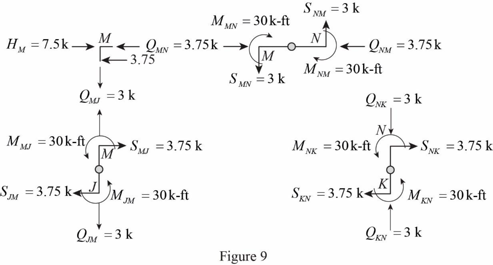
Column moment for member JM and KN:
Determine the moment at the column member JM using moment equilibrium of joints.
Apply the moment equilibrium of joints at M.
Substitute
The moment at the column member JM is
Determine the moment at the column member KN using moment equilibrium of joints.
Apply the moment equilibrium of joints at N.
Substitute
The moment at the column member KN is
Column shear for member JM and KN:
Determine the shear at the end M in the column member JM using the relation.
Substitute
The shear at the column member MJ must act towards right, so that it can produce Clockwise moment to balance the counterclockwise moment at joint M.
Determine the shear at the end of the column J using equilibrium conditions.
Substitute 3.75 k for
Determine the shear at the end N in the column member KN using the relation.
Substitute
The shear at the column member NK must act towards right, so that it can produce Clockwise moment to balance the counterclockwise moment at joint N.
Determine the shear at the end of the column K using equilibrium conditions.
Substitute 3.75 k for
Column moment for member EI, FJ, GK, and HL:
Determine the moment at the column member EI using moment equilibrium of joints.
Apply the moment equilibrium of joints at I.
Substitute
The moment at the column member EI is
Determine the moment at the column member FJ.
Apply the moment equilibrium of joints at J.
Substitute
The moment at the column member FJ is
Determine the moment at the column member GK.
Apply the moment equilibrium of joints at K.
Substitute
The moment at the column member GK is
Determine the moment at the column member HL using moment equilibrium of joints.
Apply the moment equilibrium of joints at L.
Substitute
The moment at the column member IF is
Column shear for member EI, FJ, GK, and HL:
Determine the shear at the end I in the column member EI using the relation.
Substitute
The shear at the column member IE must act towards right, so that it can produce Clockwise moment to balance the counterclockwise moment at joint I.
Determine the shear at the end of the column E using equilibrium conditions.
Substitute 6.62 k for
Determine the shear at the end J in the column member FJ using the relation.
Substitute
The shear at the column member JF must act towards right, so that it can produce Clockwise moment to balance the counterclockwise moment at joint J.
Determine the shear at the end of the column F using equilibrium conditions.
Substitute 4.64 k for
Determine the shear at the end K in the column member GK using the relation.
Substitute
The shear at the column member KG must act towards right, so that it can produce Clockwise moment to balance the counterclockwise moment at joint K.
Determine the shear at the end of the column G using equilibrium conditions.
Substitute 4.64 k for
Determine the shear at the end L in the column member HL using the relation.
Substitute
The shear at the column member LH must act towards right, so that it can produce Clockwise moment to balance the counterclockwise moment at joint L.
Determine the shear at the end of the column H using equilibrium conditions.
Substitute 6.62 k for
Column moment for member AE, BF, CG, and DH:
Determine the moment at the column member AE using moment equilibrium of joints.
Apply the moment equilibrium of joints at E.
Substitute
The moment at the column member AE is
Determine the moment at the column member BF.
Apply the moment equilibrium of joints at F.
Substitute
The moment at the column member BF is
Determine the moment at the column member CG using moment equilibrium of joints.
Apply the moment equilibrium of joints at C.
Substitute
The moment at the column member CG is
Determine the moment at the column member DH using moment equilibrium of joints.
Apply the moment equilibrium of joints at H.
Substitute
The moment at the column member DH is
Column shear for member AE, BF, CG, and DH:
Determine the shear at the end E in the column member AE using the relation.
Substitute
The shear at the column member EA must act towards right, so that it can produce Clockwise moment to balance the counterclockwise moment at joint E.
Determine the shear at the lower end of the column A using equilibrium conditions.
Substitute 3.97 k for
Determine the shear at the end F in the column member BF using the relation.
Substitute
The shear at the column memer FB must act towards right, so that it can produce Clockwise moment to balance the counterclockwise moment at joint F.
Determine the shear at the lower end of the column B using equilibrium conditions.
Substitute 14.78 k for
Determine the shear at the end G in the column member CG using the relation.
Substitute
The shear at the column member GC must act towards right, so that it can produce counterclockwise moment to balance the clockwise moment at joint G.
Determine the shear at the lower end of the column C using equilibrium conditions.
Substitute 14.78 k for
Determine the shear at the end H in the column member DH using the relation.
Substitute
The shear at the column member HD must act towards right, so that it can produce Clockwise moment to balance the counterclockwise moment at joint H.
Determine the shear at the lower end of the column A using equilibrium conditions.
Substitute 3.97 k for
Draw the free body diagram of frame with the column moments and shears for the portion EIJ as in Figure (9).
Girder axial forces:
Girder MN.
Determine the girder end action at the upper left end joint M using the equilibrium condition.
Apply equilibrium condition at left end joint M.
Substitute 3.75 k for
The girder end action at joint M in the girder MN is
Determine the girder end action at the upper right end joint H using the equilibrium condition.
Apply equilibrium condition at end joint M.
Substitute 3.75 k for
Girder IJ.
Determine the girder end action at the upper left end joint I using the equilibrium condition.
Apply equilibrium condition at left end joint I.
Substitute 6.62 k for
The girder end action at joint I in the girder IJ is
Determine the girder end action at the upper right end joint H using the equilibrium condition.
Apply equilibrium condition at end joint J.
Substitute 8.38 k for
Girder JK.
Determine the girder end action at the left end joint J for the girder JK using the relation.
Substitute 8.38 k for
Determine the girder end action at the right end joint K.
Substitute 7.49 k for
Girder KL.
Determine the girder end action at the left end joint K for the girder KL using the relation.
Substitute 7.49 k for
Determine the girder end action at the right end joint L.
Substitute 6.62 k for
Girder EF.
Apply equilibrium condition at left end joint E.
Substitute 3.97 k for
The girder end action at joint E in the girder EF is
Determine the girder end action at the right end joint F using the equilibrium condition.
Apply equilibrium condition at left end joint F.
Substitute 17.65 k for
Determine the girder end action at the left end joint F for the girder FG using equilibrium condition.
Substitute 17.65 k for
Determine the girder end action at the right end joint G.
Substitute 7.51 k for
Determine the girder end action at the left end joint G for the girder GH using equilibrium condition.
Substitute 7.51 k for
Determine the girder end action at the right end joint H.
Substitute 2.63 k for
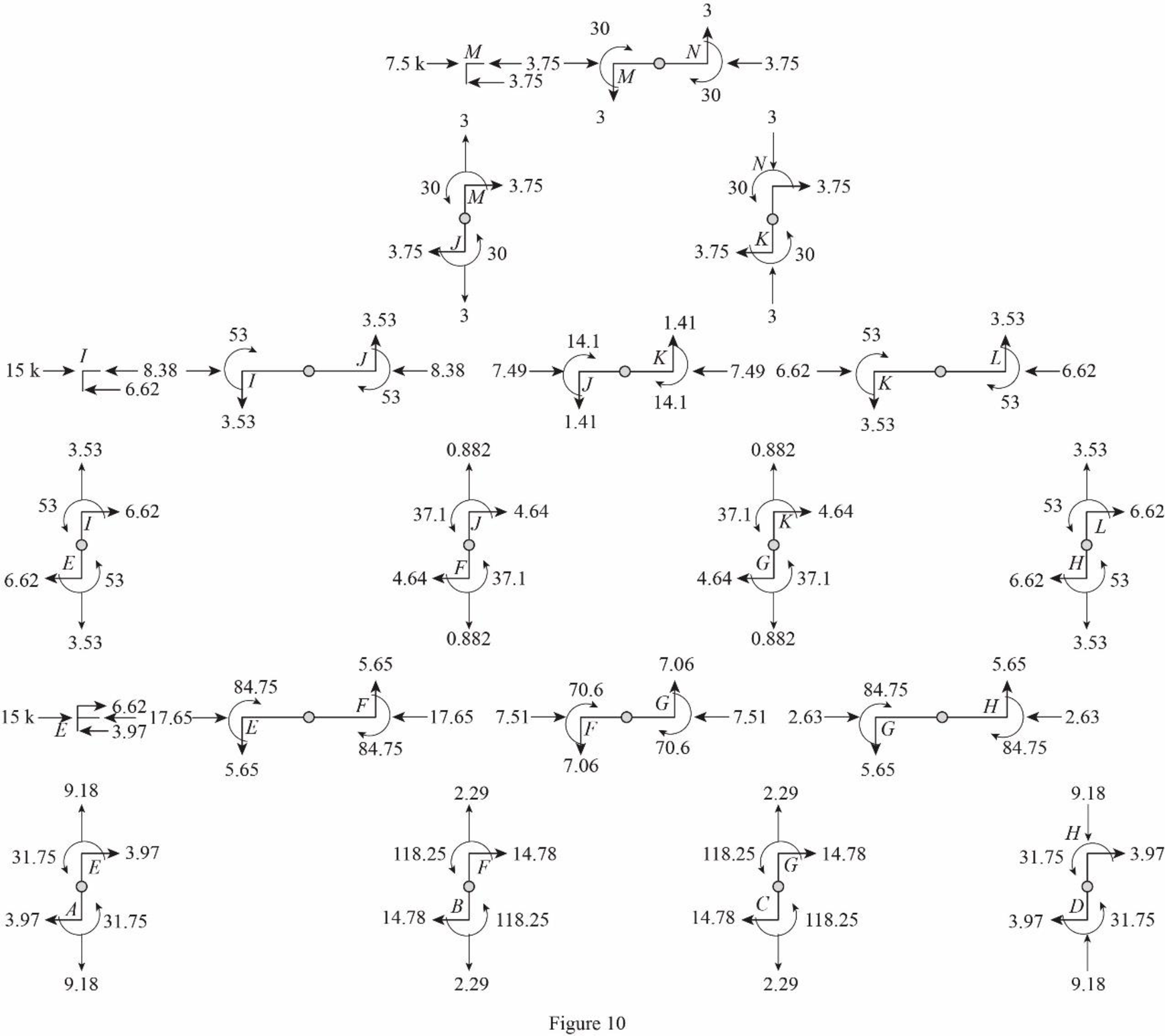
Draw the freebody diagram of the member end forces and moments as in Figure (10).
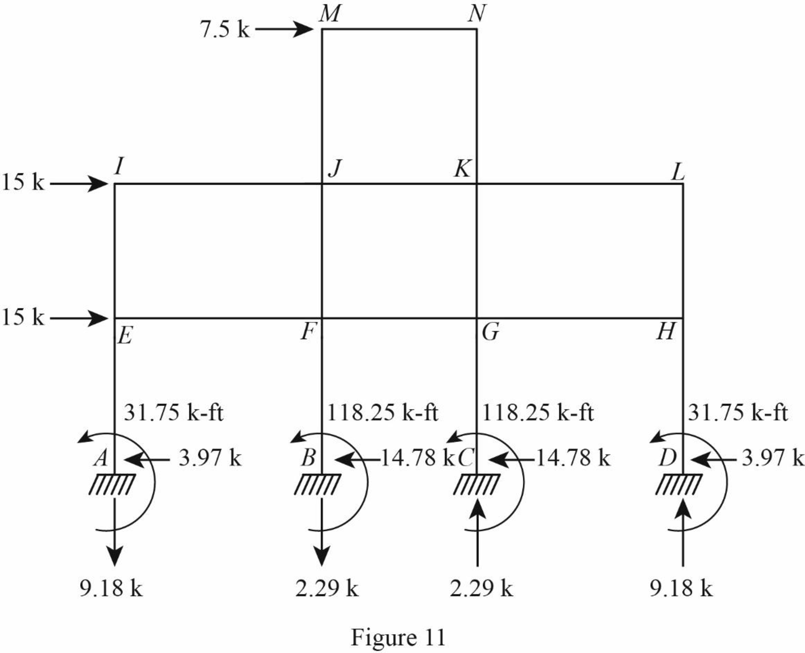
Draw the freebody diagram of the frame with support reactions and moment as in Figure (11).
Want to see more full solutions like this?
Chapter 12 Solutions
Structural Analysis (MindTap Course List)

- Consider a pool of saturated water at atmospheric pressure. The base of the pool is made of thick polished copper square plate of length 1 m. To generate steam, exhaust gas is flowing underneath and parallel to the base plate with velocity 3 m/s and average temperate of 1090°C. The bottom surface the plate is at constant temperature of 110°. Use the properties of air for exhaust gas. a) Determine the boiling heat transfer rate. b) Determine the temperature of the top surface of the plate. Comment on the results. c) Examine the impact of your assumptions on your solutions. (what will change if any of the assumptions is not valid?)arrow_forward-The axial deflection pipe in inches. -The lateral deflection of the beam in inches -The total deflection of the beam like structure in inches ? all to 4 sig figs AI did not help. as i input what i get im not sure if its a rounding error or what.arrow_forward1. For the foundation shown below: Qapp = 60 kips (Load obtained from structural engineer) 1.5 ft G.W.T. 3 ft Poorly Graded Sand (SP): Ym 115 pcf (above G.W.T.) Ysat 125 pcf (below G.W.T.) c' = 0, ' = 35° K Square footing, 4' x 4' Foundation Dimension Information: 1-ft x 1-ft square concrete column. 1-ft thick "foot" flanges. Yconc=150 pcf *Assume weight of reinforcing steel included in unit weight of concrete. *Assume compacted backfill weighs the same as in-situ soil. Assume this foundation is being designed for a warehouse that had a thorough preliminary soil exploration. Using the general bearing capacity equation: a. Calculate the gross applied bearing pressure, the gross ultimate bearing pressure, and determine if the foundation system is safe using a gross bearing capacity ASD approach. Please include the weight of the foundation, the weight of the backfill soil, and the effect of the uplift pressure caused by the presence of the water table in your bearing capacity…arrow_forward
- ٢٥ ٠٥:٤٠١٠ 2025 ChatGPT VivaCut Onet Puzzle مسلم X Excel JPG I❤> PDF Copilot Chat Bot PDF2IMG iLovePDF NokoPrint O.O StudyX ☑ W CapCut Candy Crush DeepSeek Word ☐ Saga 啡 AcadAl ل TikTokarrow_forwardRefer to the figure below. Given: L = 7 m, y = 16.7 kN/m², and ø' = 30°. L L3 ση Sand γ $' D T LA L σε σε IN P Sand 1. Calculate the theoretical depth of penetration, D. (Enter your answer to three significant figures.) D= m 2. Calculate the maximum moment. (Enter your answer to three significant figures.) Mmax kN-m/marrow_forwardWhy is it important for construction project managers to be flexible when dealing with the many variable factors that pop up in a project?arrow_forward
