
Find the approximate axial forces, shears, and moments for the all members of the frames using cantilever method.
Explanation of Solution
Given information:
The axial force acting at point I (HI) is 20 kN.
The axial force acting at point E (HE) is 40 kN.
The vertical distance of the member AE, BF, CG, and DH (L2) is 6 m.
The vertical distance of the member EI, FJ, GK, and HL (L1) is 4 m.
The horizontal distance of the members AB, EF, and IJ (l1) is 8 m.
The horizontal distance of the members BC, FG, and JK (l2) is 6 m.
The horizontal distance of the members CD, GH, and KL (l3) is 8 m.
Take the counterclockwise moment is positive and clockwise moment is negative.
The axial force in horizontal direction, towards right is positive and towards left side is negative.
The axial force in vertical direction, towards upward is positive and towards downward is negative.
Calculation:
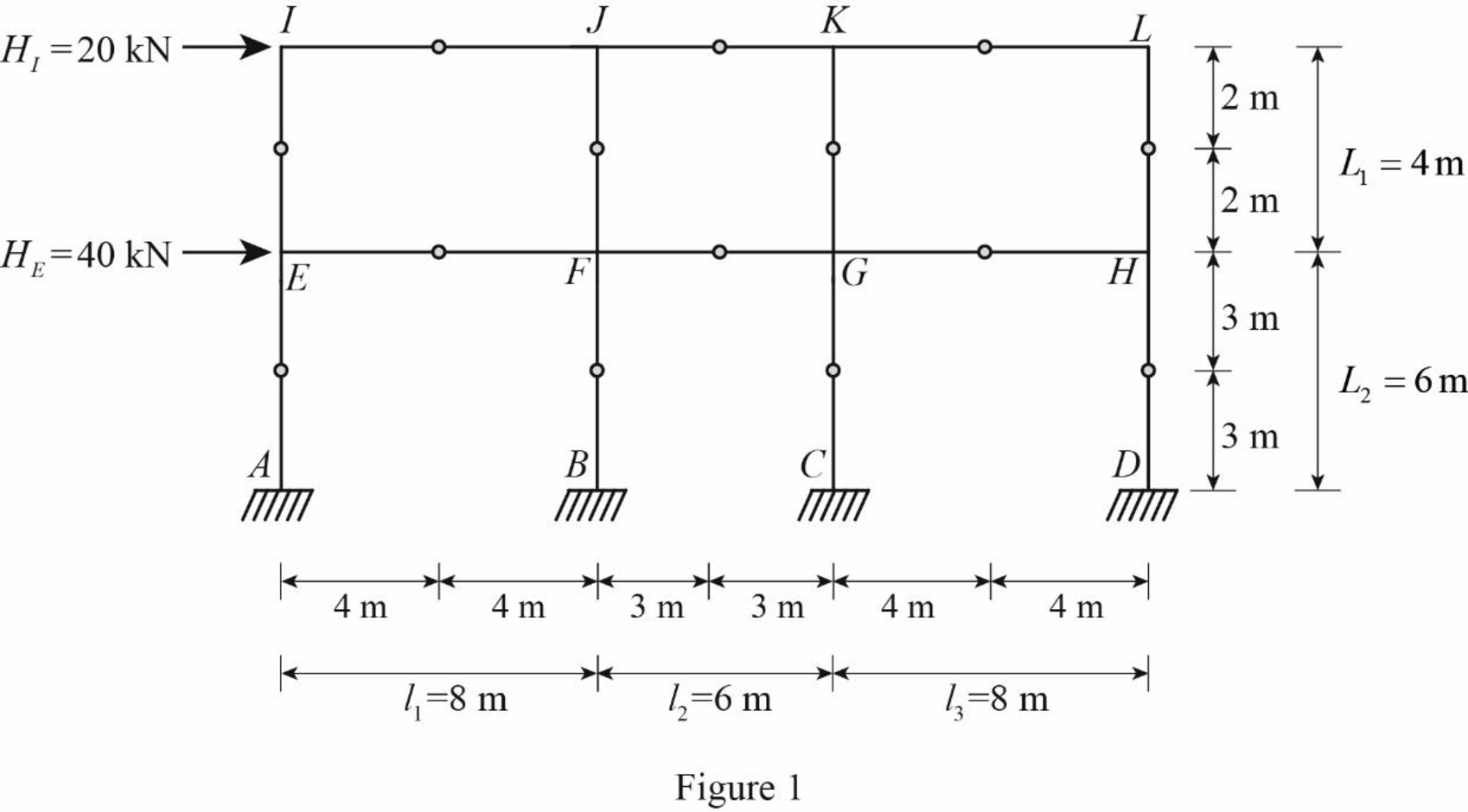
Insert the internal hinges at the midpoints of all the members of the given frame to obtain the simplified frame for approximate analysis.
Draw the simplified frame as in Figure (1).
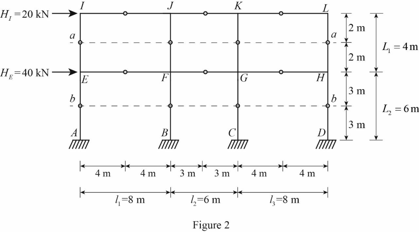
For the calculation of column axial forces of story of the frame, pass an imaginary section aa through the internal hinges at the midheights of columns EI, FJ, GK, and HL, and pass an imaginary section bb through the internal hinges at the midheights of columns AE, BF, CG, and DH.
Draw the free body diagram of the frame portion with the passed imaginary lines as in Figure (2).
Column axial forces:
Above section aa:
Draw the free body diagram of the frame portion above the section aa as in Figure (3).

Refer Figure 3.
Determine the location of the centroid using the relation.
ˉx=∑Ax∑A=∑Ax1+Ax2+Ax3+Ax44A (1)
Substitute 0 m for x1, 8 m for x2, 14 m for x3, and 22 m for x4 in Equation (1).
ˉx=A(0)+A(8)+A(14)+A(22)4A=11 m
The given lateral load is acting on the frame to the right, therefore the axial force in column EI and FJ located to the left of the centroid, must be tensile, whereas the axial force in column HL and GK placed to the right of the centroid, must be compressive.
Consider the axial forces in the columns are to be linearly proportional to their distances from centroid.
Apply similar triangle rule.
Determine the relationship in column axial force between the member EI and FJ using the relation.
QFJ=ˉx−l1ˉxQEI
Substitute 11 m for ˉx and 8 m for l1.
QFJ=11−811QEI=311QEI
Determine the relationship in column axial force between the member EI and GK using the relation.
QGK=(l1+l2)−ˉxˉxQEI
Substitute 8 m for l1, 6 m for l2, and 11 m for ˉx.
QGK=(8+6)−1111QEI=311QEI
Determine the axial force in the column members EI, FJ, GK, and HL using equilibrium conditions.
Take moment about point M.
∑MM=0QHL×(l1+l2+l3)+QGK×(l1+l2)−QFJ×l1−HI×L12=0
Substitute QEI for QHL, 8 m for l1, 6 m for l2, 8 m for l3, 311QEI for QGK, 311QEI for QFJ, 20 kN for HI, and 4 m for L1.
QEI×(8+6+8)+311QEI×(8+6)−311QEI×8−20×42=0242QEI+42QEI−24QEI=440QEI=440260QEI=1.69 kN
Determine the axial force in the column members FJ.
QFJ=311QEI
Substitute 1.69 kN for QEI.
QFJ=311×1.69=0.46 kN(↓)
Determine the axial force in the column members GK.
QGK=311QEI
Substitute 1.69 kN for QEI.
QGK=311×1.69=0.46 kN(↑)
Determine the axial force in the column members HL.
QHL=QEI
Substitute 1.69 kN for QEI.
QHL=1.69 kN(↑)
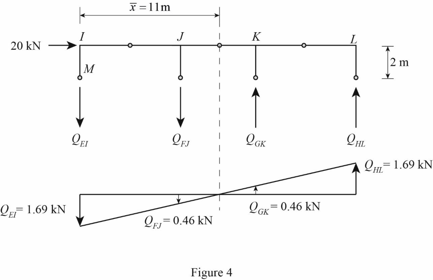
Draw the free body diagram of the frame portion above the section aa with the axial forces in the column members as in Figure (4).
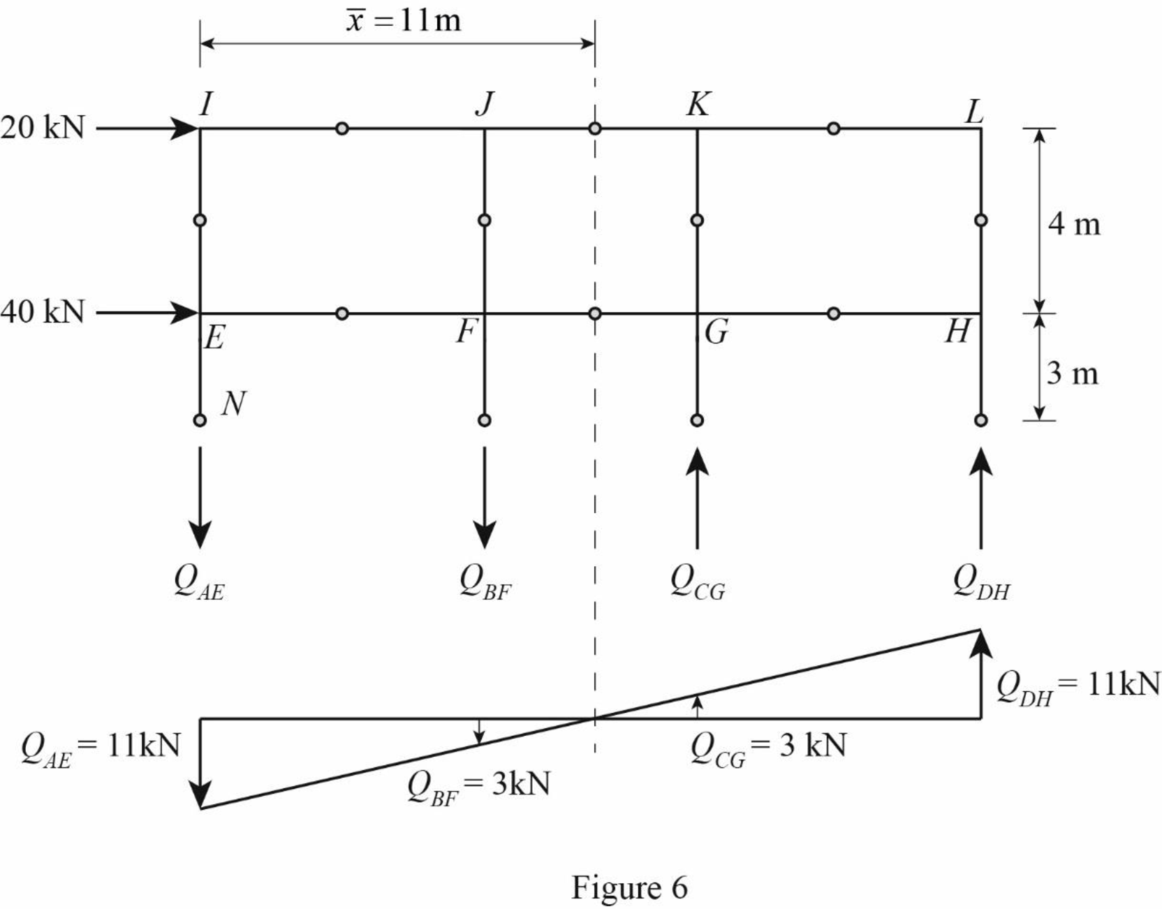
Draw the free body diagram of the frame portion above the section bb as in Figure (5).
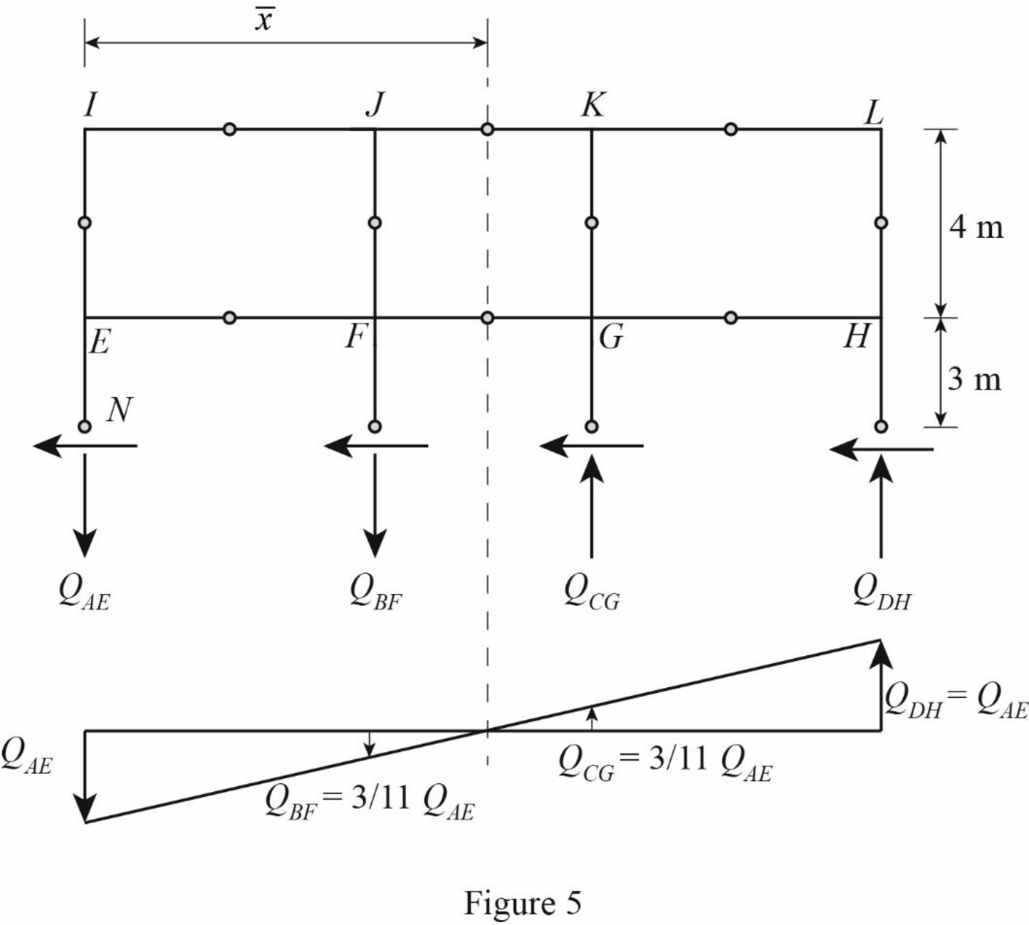
The given lateral load is acting on the frame to the right, therefore the axial force in column AE and BF located to the left of the centroid, must be tensile, whereas the axial force in column CG and DH placed to the right of the centroid, must be compressive.
Determine the relationship in column axial force between the member AE and BF using the relation.
QBF=ˉx−l1ˉxQAE
Substitute 11 m for ˉx and 8 m for l1.
QBF=11−811QAE=311QAE
Determine the relationship in column axial force between the member AE and CG using the relation.
QCG=(l1+l2)−ˉxˉxQAE
Substitute 8 m for l1, 6 m for l2, and 11 m for ˉx.
QCG=(8+6)−1111QAE=311QAE
Determine the axial force in the column members AE, BF, CG, and DH using equilibrium conditions.
Take moment about point N.
∑MN=0QDH×(l1+l2+l3)+QCG×(l1+l2)−QBF×l1−HI×(L1+L22)−HE×L22=0
Substitute QAE for QDH, 8 m for l1, 6 m for l2, 8 m for l3, 311QAE for QBF, 311QAE for QCG, 20 kN for HI, 4 m for L1, 40 kN for HE, and 6 m for L2.
QAE×(8+6+8)+311QAE×(8+6)−311QAE×8−20×(4+62)−40×62=0242QAE+42QAE−24QAE=2,860QAE=2,860260QAE=11 kN
Determine the axial force in the column members BF.
QBF=311QAE
Substitute 11 kN for QAE.
QBF=311×11=3 kN(↓)
Determine the axial force in the column members CG.
QCG=311QAE
Substitute 11 kN for QAE.
QCG=311×11=3 kN(↑)
Determine the axial force in the column members DH.
QDH=QAE
Substitute 11 kN for QAE.
QDH=11 kN(↑)
Draw the free body diagram of the frame portion above the section bb with the axial forces in the column members as in Figure (6).
Girder shear and moments:
Consider girder IJ.
Determine the shear at upper left end joint I using equilibrium equation.
∑FY=0SIJ+QIE=0
Substitute 1.69 kN for QIE.
SIJ+1.69 kN=0SIJ=−1.69 kNSIJ=1.69 kN(↓)
Determine the shear at upper right end joint J using equilibrium equation.
∑FY=0−SIJ+SJI=0
Substitute 1.69 kN for SIJ.
−1.69+SJI=0SJI=1.69 kN(↑)
Determine the moment at left end of the girder IJ using equilibrium equations.
MIJ=−SIJ×l12
Substitute 1.69 kN for SIJ and 8 m for l1.
MIJ=−1.69×82=6.76 kN⋅m(Clockwise)
Determine the moment at right end of the girder GH using equilibrium equations.
Take moment about point I.
∑MG=0−MIJ+SJI×l1+MJI=0
Substitute 6.76 kN⋅m for MIJ, 1.69 kN for SJI, and 8 m for l1.
−6.76+1.69×8+MJI=0MJI=−6.76 kN⋅mMJI=6.76 kN⋅m(Clockwise)
Consider girder JK.
Determine the shear at left end joint J using equilibrium equation.
∑FY=0SJI+SJK+QJF=0
Substitute 1.69 kN for SJI and 0.46 kN for QJF.
1.69+SJK+0.46=0SJK=−2.15 kNSJK=2.15 kN(↓)
Determine the shear at right end joint K using equilibrium equation.
∑FY=0−SJK+SKJ=0
Substitute 2.15 kN for SJK.
−2.15+SJK=0SJK=2.15 kN(↑)
Determine the moment at left end of the girder JK using equilibrium equations.
MJK=−SJK×l22
Substitute 2.15 kN for SJK and 6 m for l2.
MJK=−2.15×62=−6.45 kN⋅m=6.45 kN⋅m(Clockwise)
Determine the moment at right end of the girder JK using equilibrium equations.
Take moment about point J.
∑MJ=0−MJK+SKJ×l2+MKJ=0
Substitute 6.45 kN⋅m for MJK, 2.15 kN for SKJ, and 6 m for l2.
−6.45+2.15×6+MKJ=0MKJ=−6.45 kN⋅mMKJ=6.45 kN⋅m(Clockwise)
Consider girder KL.
Determine the shear at left end joint K using equilibrium equation.
∑FY=0SKJ+SKL−QKG=0
Substitute 2.15 kN for SKJ and 0.46 kN for QKG.
2.15+SKL−0.46=0SKL=−1.69 kNSKL=1.69 kN(↓)
Determine the shear at right end joint L using equilibrium equation.
∑FY=0−SKL+SLK=0
Substitute 1.69 kN for SKL.
−1.69+SKL=0SKL=1.69 kN(↑)
Determine the moment at left end of the girder KL using equilibrium equations.
MKL=−SKL×l32
Substitute 1.69 kN for SKL and 8 m for l3.
MKL=−1.69×82=−6.76 kN⋅m=6.76 kN⋅m(Clockwise)
Determine the moment at right end of the girder JK using equilibrium equations.
Take moment about point K.
∑MK=0−MKL+SLK×l3+MLK=0
Substitute 6.76 kN⋅m for MJK, 1.69 kN for SLK, and 8 m for l3.
−6.76+1.69×8+MLK=0MLK=−6.76 kN⋅mMLK=6.76 kN⋅m(Clockwise)
Consider girder EF.
Determine the shear at left end joint E using equilibrium equation.
∑FY=0SEF−QEI+QEA=0
Substitute 1.69 kN for QEI and 11 kN for QEA.
SEF−1.69+11=0SEF=−9.31 kNSEF=9.31 kN(↓)
Determine the shear at right end joint F using equilibrium equation.
∑FY=0−SEF+SFE=0
Substitute 9.31 kN for SEF.
−9.31+SFE=0SFE=9.31 kN(↑)
Determine the moment at left end of the girder EF using equilibrium equations.
MEF=−SEF×l12
Substitute 9.31 kN for SEF and 8 m for l1.
MEF=−9.31×82=−37.24 kN⋅m=37.24 kN⋅m(Clockwise)
Determine the moment at right end of the girder EF using equilibrium equations.
Take moment about point E.
∑ME=0−MEF+SFE×l1+MFE=0
Substitute 37.24 kN⋅m for MEF, 9.31 kN for SFE, and 8 m for l1.
−37.24+9.31×8+MFE=0MFE=−37.24 kN⋅mMFE=37.24 kN⋅m(Clockwise)
Consider girder FG.
Determine the shear at left end joint F using equilibrium equation.
∑FY=0SFE+SFG−QFJ+QFB=0
Substitute 9.31 kN for SFE, 0.46 kN for QFJ, and 3 kN for QFB.
9.31+SFG−0.46+3=0SFG=−11.85 kNSFG=11.85 kN(↓)
Determine the shear at right end joint G using equilibrium equation.
∑FY=0−SFG+SGF=0
Substitute 11.85 kN for SFG.
−11.85+SGF=0SGF=11.85 kN(↑)
Determine the moment at left end of the girder FG using equilibrium equations.
MFG=−SFG×l22
Substitute 11.85 kN for SFG and 6 m for l2.
MFG=−11.85×62=−35.55 kN⋅m=35.55 kN⋅m(Clockwise)
Determine the moment at right end of the girder FG using equilibrium equations.
Take moment about point F.
∑MF=0−MFG+SGF×l2+MGF=0
Substitute 35.55 kN⋅m for MFG, 11.85 kN for SGF, and 6 m for l2.
−35.55+11.85×6+MGF=0MGF=−35.55 kN⋅mMGF=35.55 kN⋅m(Clockwise)
Consider girder GH.
Determine the shear at left end joint G using equilibrium equation.
∑FY=0SGH+SGF+QGK−QGC=0
Substitute 11.85 kN for SGF, 0.46 kN for QGK, and 3 kN for QGC.
SGH+11.85+0.46−3=0SGH=−9.31 kNSGH=9.31 kN(↓)
Determine the shear at right end joint H using equilibrium equation.
∑FY=0−SGH+SHG=0
Substitute 9.31 kN for SGH.
−9.31+SHG=0SHG=9.31 kN(↑)
Determine the moment at left end of the girder GH using equilibrium equations.
MGH=−SGH×l32
Substitute 9.31 kN for SGH and 8 m for l3.
MGH=−9.31×82=−37.24 kN⋅m=37.24 kN⋅m(Clockwise)
Determine the moment at right end of the girder GH using equilibrium equations.
Take moment about point G.
∑MG=0−MGH+SHG×l3+MHG=0
Substitute 37.24 kN⋅m for MGH, 9.31 kN for SHG, and 8 m for l3.
−37.24+9.31×8+MHG=0MHG=−37.24 kN⋅mMHG=37.24 kN⋅m(Clockwise)
Column moments and shears:
Column moment for member EI, FJ, GK, and HL:
Determine the moment at the column member EI using moment equilibrium of joints.
Apply the moment equilibrium of joints at I.
∑M=0MIE−MIJ=0
Substitute 6.76 kN⋅m for MIJ.
MIE−6.76=0MIE=6.76 kN⋅m(Counterclockwise)
The moment at the column member EI is MEI=MIE=6.76 kN⋅m(Counterclockwise).
Determine the moment at the column member FJ.
Apply the moment equilibrium of joints at J.
∑M=0−MJI−MJK+MJF=0
Substitute 6.76 kN⋅m for MIJ and 6.45 kN⋅m for MJK.
−6.76−6.45+MJF=0MJF=13.21 kN⋅m(Counterclockwise)
The moment at the column member FJ is MJF=MFJ=13.21 kN⋅m(Counterclockwise).
Determine the moment at the column member GK.
Apply the moment equilibrium of joints at K.
∑M=0−MKJ−MKL+MKG=0
Substitute 6.45 kN⋅m for MKJ and 6.76 kN⋅m for MKL.
−6.45−6.76+MKG=0MKG=13.21 kN⋅m(Counterclockwise)
The moment at the column member GK is MKG=MGK=13.21 kN⋅m(Counterclockwise).
Determine the moment at the column member HL using moment equilibrium of joints.
Apply the moment equilibrium of joints at L.
∑M=0−MLK+MLH=0
Substitute 6.76 kN⋅m for MLK.
−6.76+MLH=0MLH=6.76 kN⋅m(Counterclockwise)
The moment at the column member HL is MHL=MLH=60 kN⋅m(Counterclockwise).
Column shear for member EI, FJ, GK, and HL:
Determine the shear at the end I in the column member EI using the relation.
SIE=MIEL12
Substitute 6.76 kN⋅m for MIE and 4 m for L1.
SIE=6.7642=3.38 kN(→)
The shear at the column member EI must act towards right, so that it can produce Clockwise moment to balance the counterclockwise moment at joint I.
Determine the shear at the end of the column E using equilibrium conditions.
∑FX=0SIE+SEI=0
Substitute 3.38 kN for SIE.
3.38+SEI=0SEI=−3.38 kNSEI=3.38 kN(←)
Determine the shear at the end J in the column member FJ using the relation.
SJF=MJFL12
Substitute 13.21 kN⋅m for MEH and 4 m for L1.
SJF=13.2142=6.61 kN(→)
The shear at the column member JF must act towards right, so that it can produce Clockwise moment to balance the counterclockwise moment at joint J.
Determine the shear at the end of the column F using equilibrium conditions.
∑FX=0SJF+SFJ=0
Substitute 6.61 kN for SJF.
6.61+SFJ=0SFJ=−6.61 kNSFJ=6.61 kN(←)
Determine the shear at the end K in the column member GK using the relation.
SKG=MKGL12
Substitute 13.21 kN⋅m for MKG and 4 m for L1.
SKG=13.2142=6.61 kN(→)
The shear at the column member KG must act towards right, so that it can produce Clockwise moment to balance the counterclockwise moment at joint K.
Determine the shear at the end of the column G using equilibrium conditions.
∑FX=0SKG+SGK=0
Substitute 6.61 kN for SKG.
6.61+SGK=0SGK=−6.61 kNSGK=6.61 kN(←)
Determine the shear at the end L in the column member HL using the relation.
SLH=MLHL12
Substitute 6.76 kN⋅m for MLH and 4 m for L1.
SLH=6.7642=3.38 kN(→)
The shear at the column member LH must act towards right, so that it can produce Clockwise moment to balance the counterclockwise moment at joint L.
Determine the shear at the end of the column H using equilibrium conditions.
∑FX=0SLH+SHL=0
Substitute 3.38 kN for SLH.
3.38+SHL=0SHL=−3.38 kNSHL=3.38 kN(←)
Column moment for member AE, BF, CG, and DH:
Determine the moment at the column member AE using moment equilibrium of joints.
Apply the moment equilibrium of joints at E.
∑M=0MEA−MEF+MEI=0
Substitute 37.24 kN⋅m for MEF and 6.76 kN⋅m for MEI.
MEA−37.24+6.76=0MEA=30.48 kN⋅m(Counterclockwise)
The moment at the column member AE is MAE=MEA=30.48 kN⋅m(Counterclockwise).
Determine the moment at the column member BF.
Apply the moment equilibrium of joints at F.
∑M=0MFB−MFE−MFG+MFJ=0
Substitute 37.24 kN⋅m for MFE, 35.55 kN⋅m for MFE, and 13.21 kN⋅m for MFJ.
MFB−37.24−35.55+13.21=0MFB=59.58 kN⋅m(Counterlockwise)
The moment at the column member BF is MFB=MBF=59.58 kN⋅m(Counterlockwise).
Determine the moment at the column member CG using moment equilibrium of joints.
Apply the moment equilibrium of joints at C.
∑M=0MGC−MGF−MGH+MGK=0
Substitute 35.55 kN⋅m for MGF, 37.24 kN⋅m for MGH, and 13.21 kN⋅m for MGK.
MGC−35.55−37.24+13.21=0MGC=59.58 kN⋅m(Counterlockwise)
The moment at the column member CG is MCG=MGC=59.58 kN⋅m(Counterlockwise).
Determine the moment at the column member DH using moment equilibrium of joints.
Apply the moment equilibrium of joints at H.
∑M=0MHD−MHG+MHL=0
Substitute 37.24 kN⋅m for MHG and 6.76 kN⋅m for MHL.
MHD−37.24+6.76=0MHD=30.48 kN⋅m(Counterclockwise)
The moment at the column member DH is MDH=MHD=30.48 kN⋅m(Counterclockwise).
Column shear for member AE, BF, CG, and DH:
Determine the shear at the end E in the column member AE using the relation.
SEA=MEAL22
Substitute 30.48 kN⋅m for MDA and 6 m for L2.
SEA=30.4862=10.16 kN(→)
The shear at the column member EA must act towards right, so that it can produce Clockwise moment to balance the counterclockwise moment at joint E.
Determine the shear at the lower end of the column A using equilibrium conditions.
∑FX=0SEA+SAE=0
Substitute 10.16 kN for SEA.
10.16+SAE=0SAE=−10.16 kNSAE=10.16 kN(←)
Determine the shear at the end F in the column member BF using the relation.
SFB=MFBL22
Substitute 59.58 kN⋅m for MEB and 6 m for L2.
SFB=59.5862=19.86 kN(→)
The shear at the column memer FB must act towards right, so that it can produce Clockwise moment to balance the counterclockwise moment at joint F.
Determine the shear at the lower end of the column B using equilibrium conditions.
∑FX=0SFB+SBF=0
Substitute 19.86 kN for SEB.
19.86+SBF=0SBF=−19.86 kNSBF=19.86 kN(←)
Determine the shear at the end G in the column member CG using the relation.
SGC=MGCL22
Substitute 59.58 kN⋅m for MGC and 6 m for L2.
SGC=59.5862=19.86 kN(→)
The shear at the column member GC must act towards right, so that it can produce counterclockwise moment to balance the clockwise moment at joint G.
Determine the shear at the lower end of the column C using equilibrium conditions.
∑FX=0SGC+SCG=0
Substitute 19.86 kN for SGC.
19.86+SCG=0SCG=−19.86 kNSCG=19.86kN(←)
Determine the shear at the end H in the column member DH using the relation.
SHD=MHDL22
Substitute 30.48 kN⋅m for MHD and 6 m for L2.
SHD=30.4862=10.16 kN(→)
The shear at the column member HD must act towards right, so that it can produce Clockwise moment to balance the counterclockwise moment at joint H.
Determine the shear at the lower end of the column A using equilibrium conditions.
∑FX=0SHD+SDH=0
Substitute 10.16 kN for SHD.
10.16+SDH=0SDH=−10.16 kNSDH=10.16 kN(←)
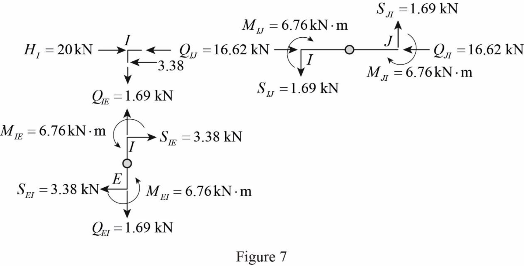
Draw the free body diagram of frame with the column moments and shears for the portion EIJ as in Figure (7).
Girder axial forces:
Girder IJ.
Determine the girder end action at the upper left end joint I using the equilibrium condition.
Apply equilibrium condition at left end joint I.
∑FX=0QIJ−SIE+HI=0
Substitute3.38 kN for SIE and 20 kN for HI.
QIJ−3.38+20=0QIJ=−16.62 kNQIJ=16.62 kN(←)
The girder end action at joint I in the girder IJ is QIJ=16.62 kN(→).
Determine the girder end action at the upper right end joint H using the equilibrium condition.
Apply equilibrium condition at end joint J.
∑FX=0QIJ+QJI=0
Substitute 16.62 kN for QIJ.
16.62+QJI=0QJI=−16.62 kNQJI=16.62 kN(←)
Girder JK.
Determine the girder end action at the left end joint J for the girder JK using the relation.
∑FX=0−QJI+QJK+SJF=0
Substitute 16.62 kN for QJI and 6.61 kN for SJF.
−16.62+QJK+6.61=0QJK=10.01 kN(→)
Determine the girder end action at the right end joint K.
∑FX=0QJK+QKJ=0
Substitute 10.01 kN for QJK.
10.01+QKJ=0QKJ=−10.01 kNQKJ=10.01 kN(←)
Girder KL.
Determine the girder end action at the left end joint K for the girder KL using the relation.
∑FX=0−QKJ+QKL+SKG=0
Substitute 10.01 kN for QKJ and 6.61 kN for SKG.
−10.01+QKL+6.61=0QKL=3.4 kN(→)
Determine the girder end action at the right end joint L.
∑FX=0QKL+QLK=0
Substitute 3.4 kN for QKL.
3.4+QLK=0QLK=−3.4 kNQLK=3.4 kN(←)
Girder EF.
Apply equilibrium condition at left end joint E.
∑FX=0−QEF−SEA+SEI+HE=0
Substitute 10.16 kN for SEA, 3.38 kN for SEI, and 40 kN for HE.
−QEF−10.16+3.38+40=0QEF=−33.22 kNQEF=33.22 kN(←)
The girder end action at joint E in the girder EF is QEF=33.22 kN(→).
Determine the girder end action at the right end joint F using the equilibrium condition.
Apply equilibrium condition at left end joint F.
∑FX=0QEF+QFE=0
Substitute 33.22 kN for QEF.
33.22+QFE=0QFE=−33.22 kNQFE=33.22 kN(←)
Determine the girder end action at the left end joint F for the girder FG using equilibrium condition.
∑FX=0QFG−QFE+SFB−SFJ=0
Substitute 33.22 kN for QFE, 19.86 kN for SFB, and 6.61 kN for SFJ.
QFG−33.22+19.86−6.61=0QFG=19.97 kN(→)
Determine the girder end action at the right end joint G.
∑FX=0QFG+QGF=0
Substitute 19.97 kN for QFG.
19.97+QGF=0QGF=−19.97 kNQGF=19.97 kN(←)
Determine the girder end action at the left end joint G for the girder GH using equilibrium condition.
Substitute 19.97 kN for
Determine the girder end action at the right end joint H.
Substitute 6.72 kN for
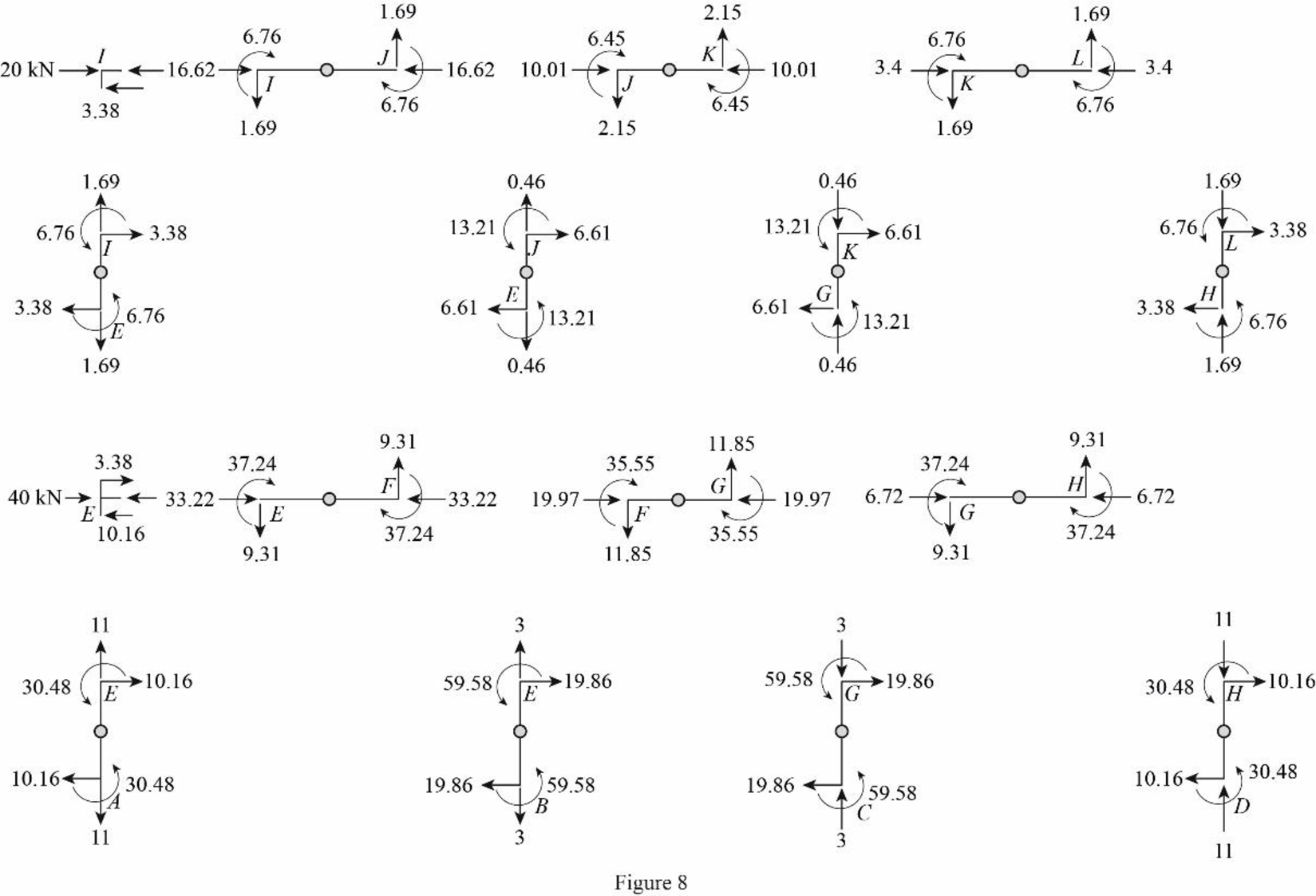
Draw the freebody diagram of the member end forces and moments as in Figure (8).
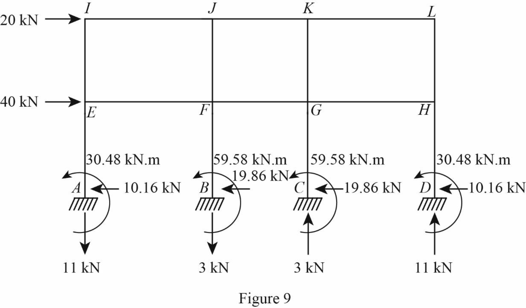
Draw the freebody diagram of the frame with support reactions as in Figure (9).
Want to see more full solutions like this?
Chapter 12 Solutions
Structural Analysis, Si Edition (mindtap Course List)

- Text Book Problem 7.82 (page 261) Consider the total head-loss in the system forthis flow is 18.56 ft (head-losses in first and second pipe are 13.83 ft and 4.73 ftrespectively). Please show numerical values for EGL/HGL at the beginning/end/intermediatechange point. (Point distribution: elevation determination 5 points, EGL, HGL lines 4points).(I think we are just using the values provided for head losses to solve this problem)arrow_forwardCalculate the BMs (bending moments) at all the joints of the beam shown in Fig.1 using the moment distribution method, and draw the Shear force diagram and Bending moment diagram for the beam shown. The beam is subjected to an UDL of w=65m. L=4.5m L1= 1.8m. Assume the support at C is pinned, and A and B are roller supports. E = 200GPa, I = 250x106 mm4.arrow_forwardCalculate the BMs (bending moments) at all the joints of the beam shown in Fig.1 using the Slope deflection method. The beam is subjected to an UDL of w=65m. L=4.5m L1= 1.8m. Assume the support at C is pinned, and A and B are roller supports. E = 200GPa, I = 250x106 mm4.arrow_forward
- Thank you for your help if you would also provide the equations used .arrow_forwardThe sectors are divided as follows:top right = 1, top left = 2, middle = 3, bottom = 4.(a) Determine the distance yˉ to the centroid of the beam’s cross-sectional area.Solve the next questions by building a table. (Table format Answers) (b) Determine the second moment of area (moment of inertia) about the x′ axis. (c) Determine the second moment of area (moment of inertia) about the y-axis.arrow_forwardinstructions: make sure to follow the instructions and provide complete and detailed solution create/draw a beam with uniformly distributed load and concentrated load after, find the shear and moment equation and ensure to draw it's shear and moment diagram once done, write it's conclusion or observation 4:57 PMarrow_forward
- Solve for forces on pin C and Darrow_forwardBorrow pit soil is being used to fill an 900,00 yd3 of depression. The properties of borrowpit and in-place fill soils obtained from laboratory test results are as follows:• Borrow pit soil: bulk density 105 pcf, moisture content = 8%, and specific gravity = 2.65• In-place fill soil: dry unit weight =120 pcf, and moisture content = 16%(a) How many yd3 of borrow soil is required?(b) What water mass is needed to achieve 16% moisture in the fill soil?(c) What is the in-place density after a long rain?arrow_forwardsolve for dt/dx=f(t,x)=x+t^2arrow_forward
- Calculate the BMs (bending moments) at all the joints of the beam shown in Fig.1 using the slope deflection method, draw the resulting shear force diagran and bending moment diagram. The beam is subjected to an UDL of w=65m. L=4.5m, L1= 1.8m. Assume the support at C is pinned, and A and B are roller supports. E = 200 GPa, I = 250x106 mm4.arrow_forwardProblem 2 (A is fixed and C is a pin) Find the reactions and A and C. 10 k- 6 ft 6 ft B A 2 k/ft 15 ftarrow_forward6. A lake with no outlet is fed by a river with a constant flow of 1200 ft3/s. Water evaporates from the surface at a constant rate of 13 ft3/s per square mile of surface area. The surface area varies with the depth h (in feet) as A (square miles) = 4.5 + 5.5h. What is the equilibrium depth of the lake? Below what river discharge (volume flow rate) will the lake dry up?arrow_forward
