
Concept explainers
Videos
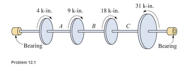
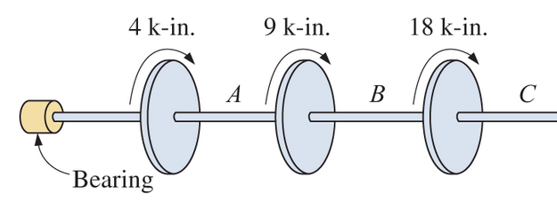
Determine the internal resisting torque in the shaft shown at A, B, and C. Show the free-body diagrams.
The externally resisting torque in the shaft at points A, B, and C
Answer to Problem 12.1P
Explanation of Solution
Given Information:
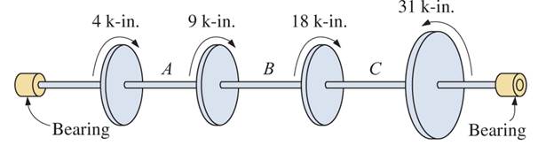
The shaft and torque acting on it are shown in the figure below:
Let internal resisting torque at
Cutting a section at A, take the free body diagram from the left bearing to point A
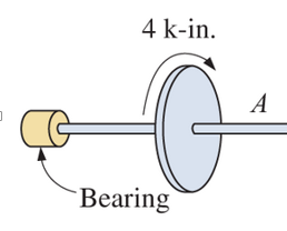
At point A, for equilibrium the summation of torques must be zero
At point B, the free body diagram from the left bearing
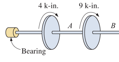
For equilibrium, the summation of torques must be zero
At point C, the free body diagram from the left bearing
For equilibrium, the summation of torques must be zero
Conclusion:
At point A, the internal resisting torque is
At point B the internal resisting torque is
At point C the internal resisting torque is
Want to see more full solutions like this?
Chapter 12 Solutions
Applied Statics and Strength of Materials (6th Edition)
Additional Engineering Textbook Solutions
Engineering Mechanics: Statics & Dynamics (14th Edition)
Applied Fluid Mechanics (7th Edition)
Thinking Like an Engineer: An Active Learning Approach (4th Edition)
INTERNATIONAL EDITION---Engineering Mechanics: Statics, 14th edition (SI unit)
Automotive Technology: Principles, Diagnosis, And Service (6th Edition) (halderman Automotive Series)
Thinking Like an Engineer: An Active Learning Approach (3rd Edition)


- In the gear system shown, the motor applies a torque of 290 N-m to the gear at A. Shaft (1) is a solid 35-mm-diameter shaft, and shaft (2) is a solid 50-mm-diameter shaft. The bearings shown allow free rotation of the shafts. Determine the torque TE provided by the gear system at gear E. B 72 teeth 30 teeth TE (2) E 24 teeth 60 teetharrow_forwardhi. can you please help me solve this as for my understanding.. our topic is about Moment of Inertia and I can't understand how it is solve. pls provide a diagram with labels. Thank you 1. Three masses A= 3kg, B= 4kg, and C= 5kg are connected by rods of negligible mass to form an equilateral triangle of side 8m as shown. Determine the individual Torques and total moment of inertia of the system about axis XY. *formula for particles: I = mR^2 (where m=mass; R= radius) *formula for system: I total= summation of I = m1R1^2 + m2R2^2 + ... +mnRn^2 thank you so much for helping me understand our topic.arrow_forwardSteel rod AB bonded to the brass rod BCD as shown below. The steel rod has a diameter of 50 mm while the brass rod has an outer diameter of 40mm with segment BC being hollow with an inner diameter of 20 mm. If the assembly is loaded as shown, solve for the a. magnitude of the internal torque in the steel section (TAB) b. maximum shear stress in the steel section (TAB) C. maximum shear stress developed in the whole assembly (Tmax) 0.60 kNm A 1.80 kNm 2.0m 2.0m 2.0marrow_forward
- A shaft ABCD is fixed at end D and has torques acting at points A, B, and C as shown below. The bearing support between A and B allows free rotation. If we know that A = −0.382 rad, A/B = 0.358 rad, and B/C = −0.233 rad, calculate the absolute twist of the shaft at point C(oc) and enter it in rad (radians) correct to 3 significant digits below. Make sure to include the sign if it is negative noting that CCW rotations are positive and CW rotations are negative. 150 N.m 280 N.m B 40 N-m Darrow_forward4) The 1.5 in diameter shaft below is supported by a thrust bearing at A and a self-aligning bearing at B. The gear weights 100 lbs and supports a 400 lb load in the axial direction (+x-direction), a 2000 lb transmitted load (+y-direction), and 600 lb radial load (-z-direction). The pulley weighs 400 lb and supports loads in the +z-direction. a. Construct the V-M-N-T diagrams for the shaft. b. Determine the location on the shaft with the most severe state of stress. c. Sketch the Mohr's circle and find the principal stresses at that location. 6 in. -12 in. - 8 in. YA 400 lb 600 lb Gear 2000 lb 4 in. 1200 lb 200 lb D 8 in. Pulleyarrow_forwardFor the steel shaft shown in Fig. Determine the torque transmitted by transverse cross sections at points A, B, and C of the shaft. 150 ft-lb 100 ft-lb 300 ft-lbarrow_forward
- The support points (bearings) at A and B only exert force on the components and z, on the steel shaft. Determine the diameter of the shaft, in millimeters, so that it can withstand the gear loads, without exceeding an allowable shear stress ? allowable = 80 MPa.to. Free-Body diagram.b. Shear force diagrams.c. Bending moment diagrams.d. Identification of the critical point of the axis.e. Calculation of the shaft diameter.arrow_forwardNeed help with number 13, please!arrow_forward3. A steel shaft 60 in. long has applied to it a 10,000 in-lb torque by a pulley located at the center of the shaft. A gear at the left end of the shaft applies 8000 in-lb of torque to the shaft while a gear located 9 in. to the left of the right end of the shaft applies 2000 in-lb of torque. Calculate the angular deflection of the shaft if the shaft is 2 in. in diameter for a length of 36 in. from the left end of the shaft and 1.5 in. in diameter in the remainder of the shaft. Neglect the effect of the keyways in the calculations. Ans. 0.424oarrow_forward
- O A. Given a homogenous shaft with length L, radius R, and modulus of rigidity G, if the internal torque along the shaft is given by the equation T(x) = 0.5x, what is the magnitude of the angle of twist at æ = L? Select one: O B L 4.JG O C. TG O D. Earrow_forward4-Determine the rotation angle between A and C, if the torque is T=0.9 N.m in point C, if G=80 GPa and diameter of all shafts are D=4 mm. (The radius of small circle are r and the bigger one are 2r) e are Coder 40 T=09N.Narrow_forward2arrow_forward
 Elements Of ElectromagneticsMechanical EngineeringISBN:9780190698614Author:Sadiku, Matthew N. O.Publisher:Oxford University Press
 Mechanics of Materials (10th Edition)Mechanical EngineeringISBN:9780134319650Author:Russell C. HibbelerPublisher:PEARSON
 Thermodynamics: An Engineering ApproachMechanical EngineeringISBN:9781259822674Author:Yunus A. Cengel Dr., Michael A. BolesPublisher:McGraw-Hill Education
 Control Systems EngineeringMechanical EngineeringISBN:9781118170519Author:Norman S. NisePublisher:WILEY
 Mechanics of Materials (MindTap Course List)Mechanical EngineeringISBN:9781337093347Author:Barry J. Goodno, James M. GerePublisher:Cengage Learning
 Engineering Mechanics: StaticsMechanical EngineeringISBN:9781118807330Author:James L. Meriam, L. G. Kraige, J. N. BoltonPublisher:WILEY