
Videos
(a)
The mass flow rate of the refrigerant through the upper compression cycle.
(a)
Answer to Problem 59P
The mass flow rate of the refrigerant through the upper compression cycle is
Explanation of Solution
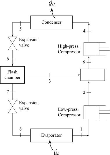
Sketch the schematic diagram for the two stage cascade refrigeration system as in Figure (1).
Write the relation between the specific enthalpies at the inlet and exit of throttling process.
Here, specific enthalpy at the inlet of throttling is
Write the expression for the isentropic efficiency of the compressor
Here, specific enthalpy at the isentropic exit of compressor is
Write the formula to calculate the dryness fraction at the exit of expansion valve
Here, specific enthalpy of refrigerant at expansion valve exit is
Write the expression for the mass flow rate of refrigerant
Here, mass flow rate of refrigerant at the inlet of low pressure compressor is
Conclusion:
From the Table A-12 of “Saturated refrigerant R-134a: Pressure”, obtain the properties of refrigerant at low pressure compressor inlet pressure
Here, specific enthalpy of the saturated vapor is
The specific entropy at the end of isentropic compression
Refer to Table A-13, “Superheated R-134a”, and obtain the values of R-134a at pressure of
Substitute
From the Table A-12 of “Saturated refrigerant R-134a: Pressure”, obtain the properties of refrigerant at throttling inlet pressure
From the Table A-12 of “Saturated refrigerant R-134a: Pressure”, obtain the properties of refrigerant at second stage compressor inlet pressure
Substitute
From the Table A-12 of “Saturated refrigerant R-134a: Pressure”, obtain the properties of refrigerant at second stage expansion inlet pressure
Substitute
From the Table A-12 of “Saturated refrigerant R-134a: Pressure”, obtain the properties of refrigerant at pressure
Substitute
Substitute
The mass flow rate of the refrigerant through the upper compression cycle is
(b)
The rate at which heat removed from the refrigerated space.
(b)
Answer to Problem 59P
The rate at which heat removed from the refrigerated space is
Explanation of Solution
Write the mass balance equation for the
Write the energy balance equation for the flash chamber.
Here, specific enthalpy at state 9 is
Write the formula to calculate the rate of heat transfer from the refrigerated space
Conclusion:
Refer to Table A-13, “Superheated R-134a”, and obtain the values of R-134a at pressure of
The specific entropy at the end of isentropic compression
Refer to Table A-13, “Superheated R-134a”, and obtain the values of R-134a at pressure of
Substitute
Substitute
Thus, the rate at which heat removed from the refrigerated space is
(c)
The power input required to the two stage cascade refrigeration system.
The coefficient of refrigeration for the two-stage cascade refrigeration system.
(c)
Answer to Problem 59P
The power input required to the two stage cascade refrigeration system is
The coefficient of refrigeration for the two-stage cascade refrigeration system is
Explanation of Solution
Write the formula to calculate the total required work input
Here, required work input to the first stage compression is
Write the formula to calculate the COP of the two-stage cascade refrigeration system.
Conclusion:
Substitute
Thus, the power input required to two stage cascade refrigeration system is
Substitute 26.35 kW for
Thus, the coefficient of refrigeration for the two-stage cascade refrigeration system is
(d)
The rate at which heat removed from the refrigerated space.
The coefficient of refrigeration for the two-stage cascade refrigeration system.
(d)
Answer to Problem 59P
The rate at which heat removed from the refrigerated space is
The coefficient of refrigeration for the two-stage cascade refrigeration system is
Explanation of Solution
Write the formula to calculate the rate of heat transfer from the refrigerated space
Here, the specific enthalpy of refrigerant at the exit of expansion valve is
Write the formula to calculate the required work input
Conclusion:
From the Table A-12 of “Saturated refrigerant R-134a: Pressure”, obtain the properties of refrigerant at low pressure compressor inlet pressure
Here, specific enthalpy of the saturated vapor is
The specific entropy at the end of isentropic compression
Refer to Table A-13, “Superheated R-134a”, and obtain the values of R-134a at pressure of
Substitute
From the Table A-12 of “Saturated refrigerant R-134a: Pressure”, obtain the properties of refrigerant at expansion valve inlet pressure
Substitute
Substitute
Thus, the rate at which heat removed from the refrigerated space is
Substitute
Substitute 25.67 kW for
Thus, the coefficient of refrigeration for the two-stage cascade refrigeration system is
Want to see more full solutions like this?
Chapter 11 Solutions
EBK THERMODYNAMICS: AN ENGINEERING APPR


- Recall that the CWH equation involves two important assumptions. Let us investigate how these assumptions affect the accuracy of state trajectories under the control inputs optimized in (a) and (b). (c.1): Discuss the assumptions about the chief and deputy orbits that are necessary for deriving CWH.arrow_forwardPROBLEM 2.50 1.8 m The concrete post (E-25 GPa and a = 9.9 x 10°/°C) is reinforced with six steel bars, each of 22-mm diameter (E, = 200 GPa and a, = 11.7 x 10°/°C). Determine the normal stresses induced in the steel and in the concrete by a temperature rise of 35°C. 6c " 0.391 MPa 240 mm 240 mm 6₁ = -9.47 MPaarrow_forwardFor some viscoelastic polymers that are subjected to stress relaxation tests, the stress decays with time according to a(t) = a(0) exp(-4) (15.10) where σ(t) and o(0) represent the time-dependent and initial (i.e., time = 0) stresses, respectively, and t and T denote elapsed time and the relaxation time, respectively; T is a time-independent constant characteristic of the material. A specimen of a viscoelastic polymer whose stress relaxation obeys Equation 15.10 was suddenly pulled in tension to a measured strain of 0.5; the stress necessary to maintain this constant strain was measured as a function of time. Determine E (10) for this material if the initial stress level was 3.5 MPa (500 psi), which dropped to 0.5 MPa (70 psi) after 30 s.arrow_forward
- For the flows in Examples 11.1 and 11.2, calculate the magnitudes of the Δ V2 / 2 terms omitted in B.E., and compare these with the magnitude of the ℱ terms.arrow_forwardCalculate ℛP.M. in Example 11.2.arrow_forwardQuestion 22: The superheated steam powers a steam turbine for the production of electrical power. The steam expands in the turbine and at an intermediate expansion pressure (0.1 MPa) a fraction is extracted for a regeneration process in a surface regenerator. The turbine has an efficiency of 90%. It is requested: Define the Power Plant Schematic Analyze the steam power system considering the steam generator system in the attached figure Determine the electrical power generated and the thermal efficiency of the plant Perform an analysis on the power generated and thermal efficiency considering a variation in the steam fractions removed for regeneration ##Data: The steam generator uses biomass from coconut shells to produce 4.5 tons/h of superheated steam; The feedwater returns to the condenser at a temperature of 45°C (point A); Monitoring of the operating conditions in the steam generator indicates that the products of combustion leave the system (point B) at a temperature of 500°C;…arrow_forward
- This is an old practice exam question.arrow_forwardSteam enters the high-pressure turbine of a steam power plant that operates on the ideal reheat Rankine cycle at 700 psia and 900°F and leaves as saturated vapor. Steam is then reheated to 800°F before it expands to a pressure of 1 psia. Heat is transferred to the steam in the boiler at a rate of 6 × 10⁴ Btu/s. Steam is cooled in the condenser by the cooling water from a nearby river, which enters the condenser at 45°F. Use steam tables. NOTE: This is a multi-part question. Once an answer is submitted, you will be unable to return to this part. Determine the pressure at which reheating takes place. Use steam tables. Find: The reheat pressure is psia. (P4)Find thermal efficiencyFind m dotarrow_forwardAir at T1 = 24°C, p1 = 1 bar, 50% relative humidity enters an insulated chamber operating at steady state with a mass flow rate of 3 kg/min and mixes with a saturated moist air stream entering at T2 = 7°C, p2 = 1 bar. A single mixed stream exits at T3 = 17°C, p3 = 1 bar. Neglect kinetic and potential energy effects Determine mass flow rate of the moist air entering at state 2, in kg/min Determine the relative humidity of the exiting stream. Determine the rate of entropy production, in kJ/min.Karrow_forward
- Air at T1 = 24°C, p1 = 1 bar, 50% relative humidity enters an insulated chamber operating at steady state with a mass flow rate of 3 kg/min and mixes with a saturated moist air stream entering at T2 = 7°C, p2 = 1 bar. A single mixed stream exits at T3 = 17°C, p3 = 1 bar. Neglect kinetic and potential energy effects Determine mass flow rate of the moist air entering at state 2, in kg/min Determine the relative humidity of the exiting stream. Determine the rate of entropy production, in kJ/min.Karrow_forwardAir at T1 = 24°C, p1 = 1 bar, 50% relative humidity enters an insulated chamber operating at steady state with a mass flow rate of 3 kg/min and mixes with a saturated moist air stream entering at T2 = 7°C, p2 = 1 bar. A single mixed stream exits at T3 = 17°C, p3 = 1 bar. Neglect kinetic and potential energy effects (a) Determine mass flow rate of the moist air entering at state 2, in kg/min (b) Determine the relative humidity of the exiting stream. (c) Determine the rate of entropy production, in kJ/min.Karrow_forwardA simple ideal Brayton cycle operates with air with minimum and maximum temperatures of 27°C and 727°C. It is designed so that the maximum cycle pressure is 2000 kPa and the minimum cycle pressure is 100 kPa. The isentropic efficiencies of the turbine and compressor are 91% and 80%, respectively, and there is a 50 kPa pressure drop across the combustion chamber. Determine the net work produced per unit mass of air each time this cycle is executed and the cycle’s thermal efficiency. Use constant specific heats at room temperature. The properties of air at room temperature are cp = 1.005 kJ/kg·K and k = 1.4. The fluid flow through the cycle is in a clockwise direction from point 1 to 4. Heat Q sub in is given to a component between points 2 and 3 of the cycle. Heat Q sub out is given out by a component between points 1 and 4. An arrow from the turbine labeled as W sub net points to the right. The net work produced per unit mass of air is kJ/kg. The thermal efficiency is %.arrow_forward
 Elements Of ElectromagneticsMechanical EngineeringISBN:9780190698614Author:Sadiku, Matthew N. O.Publisher:Oxford University Press
 Mechanics of Materials (10th Edition)Mechanical EngineeringISBN:9780134319650Author:Russell C. HibbelerPublisher:PEARSON
 Thermodynamics: An Engineering ApproachMechanical EngineeringISBN:9781259822674Author:Yunus A. Cengel Dr., Michael A. BolesPublisher:McGraw-Hill Education
 Control Systems EngineeringMechanical EngineeringISBN:9781118170519Author:Norman S. NisePublisher:WILEY
 Mechanics of Materials (MindTap Course List)Mechanical EngineeringISBN:9781337093347Author:Barry J. Goodno, James M. GerePublisher:Cengage Learning
 Engineering Mechanics: StaticsMechanical EngineeringISBN:9781118807330Author:James L. Meriam, L. G. Kraige, J. N. BoltonPublisher:WILEY