
Videos
(a)
The cooling load and the COP.
(a)
Answer to Problem 32P
The cooling load and the COP is
Explanation of Solution
Show the T-s diagram for ideal vapor-compression refrigeration cycle as in Figure (1).
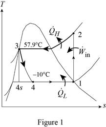
From Figure (1), write the specific enthalpy at state 3 is equal to state 4 due to throttling process.
Here, specific enthalpy at state 3 is
Express the heat removed from the cooled space.
Here, specific enthalpy at state 1, 3 and 4 is
Express heat supplied to the cooled space.
Here, specific enthalpy at state 2 is
Express the work input.
Express the COP of the cycle.
Express pressure at state 2 and state 3.
Here, pressure at state 2 and 3 is
Express quality at state 4.
Here, specific enthalpy at saturated liquid and evaporation and
Express specific entropy at state 4.
Here, specific entropy at saturated liquid and evaporation and
Conclusion:
Refer Table A-11, “saturated refrigerant-134a-temperature table”, and write the properties corresponding to initial temperature of
Here, specific entropy at state 1 is
Refer Table A-11, “saturated refrigerant-134a-tempertaure table”, and write the pressure state 2 and 3 corresponding to temperature of
Write the formula of interpolation method of two variables.
Here, the variables denote by x and y is temperature and saturated pressure respectively.
Show the saturated pressure corresponding to temperature as in Table (1).
|
Temperature |
Saturated pressure |
| 56 | 1529.1 |
| 57.9 | |
| 60 | 1682.8 |
Substitute
Substitute
Perform unit conversion of pressure at state 2 from
Refer Table A-13, “superheated refrigerant 134a”, and write the specific enthalpy at state 2 corresponding to pressure at state 2 of
Show the specific enthalpy at state 2 corresponding to specific entropy as in Table (2).
|
Specific entropy at state 2 |
Specific enthalpy at state 2 |
| 0.9164 | 280.71 |
| 0.9378 | |
| 0.9536 | 293.27 |
Use excels and substitutes the value from Table (2) in Equation (VIII) to obtain the specific enthalpy at state 2.
Refer Table A-12, “saturated refrigerant 134a-pressure table”, and write the properties corresponding to pressure at state 3 of
Here, specific enthalpy and entropy at saturated liquid is
Refer Table A-11, “saturated refrigerant-134a-tempertaure table”, and write the properties corresponding to temperature of
Substitute
Substitute
Here, specific entropy at state 4 is
Substitute
Hence, the cooling load is
Substitute
Substitute
Substitute
Hence, the COP of the cycle is
(b)
The exergy destruction in each component of the cycle and the total exergy destruction in the cycle.
(b)
Answer to Problem 32P
The exergy destruction in compressor is
Explanation of Solution
For compressor:
Express the exergy destruction in compressor.
Here, surrounding temperature is
For condenser:
Express the exergy destruction in condenser.
Here, entropy generation during process 2-3 is
For expansion valve:
For evaporator:
Express the exergy destruction in evaporator.
Here, entropy generation during process 4-1 is
Express the total exergy destruction in the cycle.
Conclusion:
Perform unit conversion of surrounding temperature from
Perform unit conversion of high temperature medium from
Perform unit conversion of low temperature medium from
Substitute
Hence, the exergy destruction in compressor is
Substitute
Hence, the exergy destruction in condenser is
Substitute
Hence, the exergy destruction in expansion valve is
Substitute
Hence, the exergy destruction in evaporator is
Substitute
Hence, the total exergy destruction in the cycle is
(c)
The second-law efficiency of the compressor, the evaporator, and the cycle.
(c)
Answer to Problem 32P
The second-law efficiency of the compressor is
Explanation of Solution
Express the exergy of the heat transferred from the low temperature medium.
Determine the second law efficiency of the cycle.
Express the total exergy destruction in the cycle.
Express the second law efficiency of the compressor.
Here, rate of work done on reversible process is
Express the exergy difference in evaporator.
Here, rate of exergy difference during process 1-4 is
Express the second law efficiency of the evaporator.
Conclusion:
Substitute
Substitute
Hence, the second-law efficiency of the cycle is
Substitute
Substitute
Hence, the second-law efficiency of the compressor is
Substitute
Substitute
Hence, the second-law efficiency of the evaporator is
Want to see more full solutions like this?
Chapter 11 Solutions
CENGEL'S 9TH EDITION OF THERMODYNAMICS:


- **Problem 8-45.** The man has a mass of 60 kg and the crate has a mass of 100 kg. If the coefficient of static friction between his shoes and the ground is \( \mu_s = 0.4 \) and between the crate and the ground is \( \mu_c = 0.3 \), determine if the man is able to move the crate using the rope-and-pulley system shown. **Diagram Explanation:** The diagram illustrates a scenario where a man is attempting to pull a crate using a rope-and-pulley system. The setup is as follows: - **Crate (C):** Positioned on the ground with a rope attached. - **Rope:** Connects the crate to a pulley system and extends to the man. - **Pulley on Tree:** The rope runs over a pulley mounted on a tree which redirects the rope. - **Angles:** - The rope between the crate and tree forms a \(30^\circ\) angle with the horizontal. - The rope between the tree and the man makes a \(45^\circ\) angle with the horizontal. - **Man (A):** Pulling on the rope with the intention of moving the crate. This arrangement tests the…arrow_forwardplease solve this problems follow what the question are asking to do please show me step by steparrow_forwardplease first write the line action find the forces and them solve the problem step by steparrow_forward
- please solve this problem what the problem are asking to solve please explain step by step and give me the correct answerarrow_forwardplease help me to solve this problem step by steparrow_forwardplease help me to solve this problem and determine the stress for each point i like to be explained step by step with the correct answerarrow_forward
- please solve this problem for me the best way that you can explained to solve please show me the step how to solvearrow_forwardplese solbe this problem and give the correct answer solve step by step find the forces and line actionarrow_forwardplease help me to solve this problems first write the line of action and them find the forces {fx=0: fy=0: mz=0: and them draw the shear and bending moment diagram. please explain step by steparrow_forward
- please solve this problem step by step like human and give correct answer step by steparrow_forwardPROBLEM 11: Determine the force, P, that must be exerted on the handles of the bolt cutter. (A) 7.5 N (B) 30.0 N (C) 52.5 N (D) 300 N (E) 325 N .B X 3 cm E 40 cm cm F = 1000 N 10 cm 3 cm boltarrow_forwardUsing the moment-area theorems, determine a) the rotation at A, b) the deflection at L/2, c) the deflection at L/4. (Hint: Use symmetry for Part a (θA= - θB, or θC=0), Use the rotation at A for Parts b and c. Note that all deformations in the scope of our topics are small deformation and for small θ, sinθ=θ).arrow_forward
 Refrigeration and Air Conditioning Technology (Mi...Mechanical EngineeringISBN:9781305578296Author:John Tomczyk, Eugene Silberstein, Bill Whitman, Bill JohnsonPublisher:Cengage Learning