
ELECTRICAL WIRING:RESIDENT.-TEXT (PB)
19th Edition
ISBN: 9781337116213
Author: MULLIN
Publisher: CENGAGE L
expand_more
expand_more
format_list_bulleted
Concept explainers
Videos
Textbook Question
Chapter 11, Problem 9R
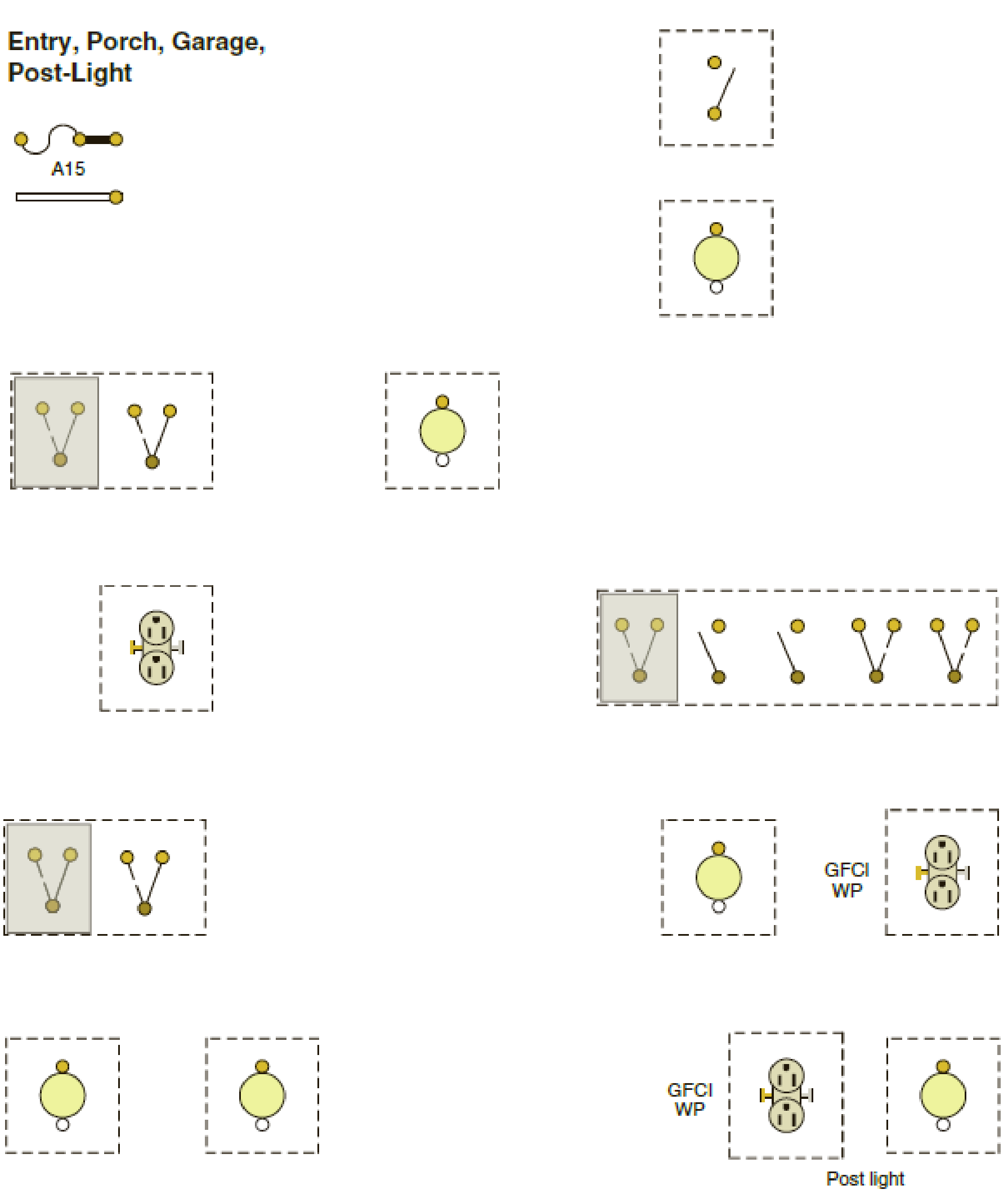
The following layout is for Lighting Circuit A15, the entry, porch, post light, and front garage lights. Using the cable layout shown in Figure 11-1, make a complete wiring diagram of this circuit. Use colored pencils to indicate the color of the conductors’ insulation.
Expert Solution & Answer

Trending nowThis is a popular solution!

Students have asked these similar questions
you dont need to solve the question i just wanna know the steps and how to find the angle between the voltage difference and the current .
thanks so much
istics of diodes, bipolar junction transistors, and
plain the structure, operation,
1. The purpose of doping in semiconductor diodes is:
a) To control their electrical properties
b) To increase their physical size
c) To enhance their mechanical strength d) To improve their thermal stability
2. In electronics production, your team wants to manufacture a very cheap diode rectifier.
Which of the following rectifier configurations would you select?
a) Half-wave rectifier
c) Full-wave rectifier
b) Bridge rectifier
d) Controlled rectifier
3. The region that a Zener diode operates to provide voltage regulation is:
a) Saturation
c) Reverse bias
b) Breakdown
d) Forward bias
4. In NMOS transistors, the depth of the channel is primarily changed by:
a) VDS
b) lp
c) VGS
d) None of these
5. NMOS transistors have
than PMOS, resulting in better current conduction:
b) Long channel
a) High mobility
c) Low mobility
d) Short channel
6. You are working in electronic production, and your team is asked to…
8.46 The generator circuit shown in Fig. P8.46 (on page 494) isconnected to a distant load via a long coaxial transmission line.The overall circuit can be modeled as in Fig. P8.46(b), in whichthe transmission line is represented by an equivalent impedanceZline = (5+ j2) W.(a) Determine the power factor of voltage source Vs.(b) Specify the capacitance of a shunt capacitor C that wouldraise the power factor of the source to unity when connectedbetween terminals (a,b). The source frequency is 1.5 kHz.
Chapter 11 Solutions
ELECTRICAL WIRING:RESIDENT.-TEXT (PB)
Ch. 11 - How many circuit wires enter the entry ceiling...Ch. 11 - Assuming that an outlet box for the entry ceiling...Ch. 11 - How many receptacle outlets and lighting outlets...Ch. 11 - Outdoor luminaires directly exposed to the weather...Ch. 11 - Prob. 5RCh. 11 - From left to right, facing the switches, what do...Ch. 11 - Who is to select the entry ceiling luminaire? ____Ch. 11 - When installing the wiring for a doorjamb switch,...Ch. 11 - The following layout is for Lighting Circuit A15,...
Knowledge Booster


Learn more about
Need a deep-dive on the concept behind this application? Look no further. Learn more about this topic, electrical-engineering and related others by exploring similar questions and additional content below.Similar questions
- 7. MOSFET circuit The MOSFET in the circuit below has V₁ = 1 V and kn = 4 mA/V². a) Is the MOSFET operating in saturation or in the triode region? b) Determine the drain current ID and Vout. + 5 V 5 k Voutarrow_forwardDraw a logic diagram of a 4-bit adder/subtractor then use it to design an Exess-3 to BCD code converter circuit. The circuit has an input (x4 xs x2x) and output (ye ya ya yi)scrarrow_forwardIf waveforms shown in figure below are applied as inputs to a 2-bit comparator (P=P: Po and Q=Q: Q), draw the three output waveforms of the comparator (P>Q, P=Q, Parrow_forwardmicro wavearrow_forwardmicro wavearrow_forwardFor this question, please show how to get the answer using block diagrams. I have included my attempt but I am not close to the answer and I don't understand how to get the T_d(s) expression. Please show the block diagram steps, as in, do not just plug this question into an AI. thank youarrow_forwardOnly expert should attempt this questions, handwritten solution onlyarrow_forwardPlease show formula used and steps as I will study themarrow_forwardQuestion One R C ww (t)T Figure 2: R-C Circuit A series R-C circuit in figure 2, has a step input voltage applied to it. Use Laplace transforms to determine expressions for (a) Current, i(t) flowing in the circuit, given that when t = Os, i=0A [12 marks] (b) Use the expression obtained in (a), calculate the current i(t) flowing in the circuit, when V = 15volts, R = 50, C=1F, t = 1sec [2 marks]arrow_forward7. MOSFET circuit The MOSFET in the circuit below has V₁ = 1 V and kn = 4 mA/V². a) Is the MOSFET operating in saturation or in the triode region? b) Determine the drain current ID and Vout. + 5 V 5 k Voutarrow_forwardNot use ai pleasearrow_forward5. MOSFET circuit The MOSFET in the circuit below has Vt = 0.5 V and kn = 0.4 mA/V2. Determine Vout. + 5 V 1 mA - Vout 6. MOSFET circuit The MOSFET in the circuit below has V₁ = 1 V and kn = 2 mA/V². a) Is the MOSFET operating in saturation or in the triode region? b) Determine the drain current ID. +2V 2 V -2 Varrow_forwardarrow_back_iosSEE MORE QUESTIONSarrow_forward_ios
Recommended textbooks for you
 EBK ELECTRICAL WIRING RESIDENTIALElectrical EngineeringISBN:9781337516549Author:SimmonsPublisher:CENGAGE LEARNING - CONSIGNMENT
EBK ELECTRICAL WIRING RESIDENTIAL
Electrical Engineering
ISBN:9781337516549
Author:Simmons
Publisher:CENGAGE LEARNING - CONSIGNMENT
Types of House Wiring - Types of Electrical Wiring - Electrical Wiring; Author: Learning Engineering;https://www.youtube.com/watch?v=A5P-buWX-dA;License: Standard Youtube License