
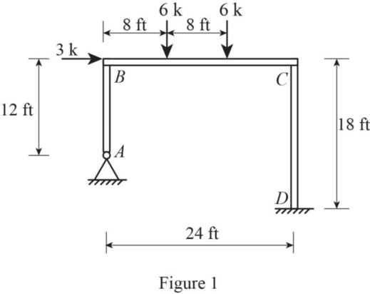
Analyze the structure calculate the horizontal displacement of joint B.
Explanation of Solution
Given information:
The Young’s modulus E is constant and equals to
Calculation:
Sketch the free body diagram of frame as shown in Figure 1.
Find the stiffness of each member connected to joint B as follows;
Find the total stiffness at joint B as follows;
Find the stiffness of each member connected to joint C as follows;
Find the total stiffness at joint C as follows;
Find the distribution factors at joint B using the relation;
Find the distribution factors at joint C using the relation;
Refer the appendix Table A.4 to find the fixed end moments.
Find the fixed end moment at each end of the member BC as follows;
| Joint | A | B | C | D | ||
| Member | AB | BA | BC | CB | CD | DC |
| DF | 0.43 | 0.57 | 0.55 | 0.45 | ||
| FEM | -32 | 32 | ||||
| Balancing | 13.76 | 18.24 | -17.6 | -14.4 | ||
| CO | -8.8 | 9.12 | -7.2 | |||
| Balancing | 3.78 | 5.02 | -5.02 | -4.1 | ||
| CO | -2.51 | 2.51 | -2.1 | |||
| Balancing | 1.08 | 1.43 | -1.38 | -1.13 | ||
| CO | -0.69 | 0.72 | -0.57 | |||
| Balancing | 0.3 | 0.39 | -0.4 | -0.32 | ||
| CO | -0.2 | 0.2 | -0.16 | |||
| Balancing | 0.09 | 0.11 | -0.11 | -0.09 | ||
| 19 | -19 | 20.06 | -20.06 | -10.03 | ||
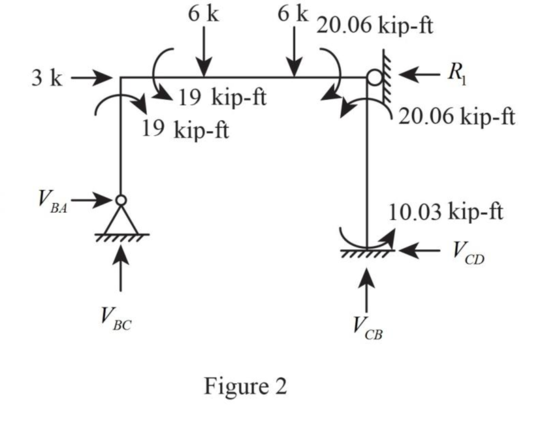
Sketch the free body diagram as shown in Figure 2.
Show the members AB, BC, and CD as in Figure 3.
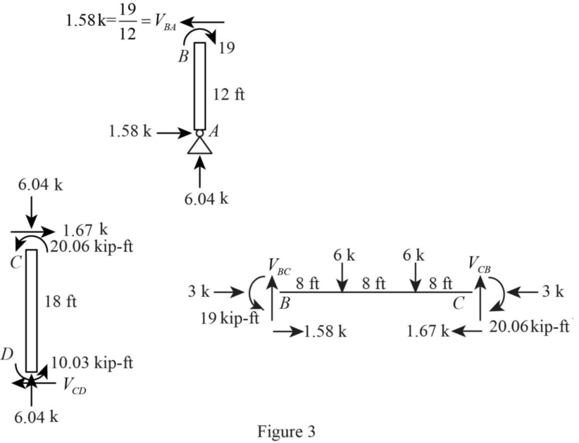
Taking moment about B ,
Summation of vertical force is equal to zero.
Taking moment about A ,
Taking moment about D,
Summation of horizontal force is equal to zero.
Find the fixed end moment at each end of the member AB as follows;
Consider the
Find the fixed end moment at each end of the member CD as follows;
| Joint | A | B | C | D | ||
| Member | AB | BA | BC | CB | CD | DC |
| DF | 0.43 | 0.57 | 0.55 | 0.45 | ||
| FEM | -86.8 | -86.8 | -48.22 | -48.22 | ||
| Balancing | 86.8 | 37.32 | 49.48 | 26.52 | 21.7 | |
| CO | 43.4 | 13.26 | 24.74 | 10.85 | ||
| Balancing | -24.36 | -32.3 | -13.61 | -11.13 | ||
| CO | -6.81 | -16.15 | -5.57 | |||
| Balancing | 2.93 | 3.88 | 8.88 | 7.27 | ||
| CO | 4.44 | 1.94 | 3.64 | |||
| Balancing | -1.91 | -2.53 | -1.07 | -0.87 | ||
| CO | -0.54 | -1.27 | -0.44 | |||
| Balancing | 0.23 | 0.31 | 0.7 | 0.57 | ||
| CO | 0.35 | 0.16 | 0.29 | |||
| Balancing | -0.15 | -0.2 | -0.09 | -0.06 | ||
| CO | -0.05 | -0.1 | -0.03 | |||
| Balancing | 0.02 | 0.03 | 0.06 | 0.04 | ||
| 0 | -29.32 | 29.32 | 30.75 | -30.75 | -39.98 | |
Show the member AB,BC, CD, as shown in figure 4.
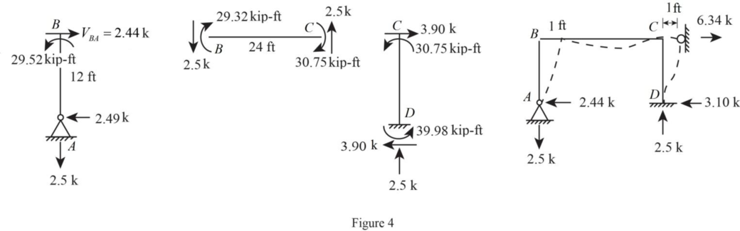
Consider span AB:
Take moment about B is Equal to zero.
Summation of forces along x-direction is Equal to zero.
Consider span BC:
Take moment about B is Equal to zero.
Summation of forces along y-direction is Equal to zero.
Consider span CD.
Take moment about C is Equal to zero.
Summation of forces along x-direction is Equal to zero.
Consider the entire structure.
Summation of forces along x-direction is Equal to zero.
Take moment about A is Equal to zero.
Summation of forces along y-direction is Equal to zero.
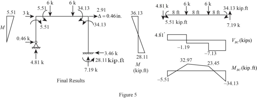
Sketch the free body diagram of shear and moment as shown in Figure 5.
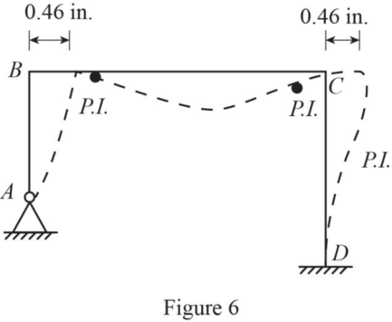
Sketch the deflected shape as shown in Figure 6.
Want to see more full solutions like this?
Chapter 11 Solutions
UCD FUND OF STRUCTURAL ANALYSIS 5E

- I dont understand how to do the hand calculations help pls A multi-cell box beam, 1800 mm long, is subject to a vertical shear load of 6 kN applied in a vertical plane. Points 1-8 mark the boom elements on the beam. Calculate the shear flow in each web and locate the shear centre using hand calculations. The results, including mesh convergence, shear flow, stress distribution, deformation, and shear centre location, will then be compared with findings from Abaqus FEA. The material properties are: Young's modulus (E) is 72 GPa, and Poisson's ratio (ν) is 0.3.arrow_forwardfind the following (show all work) Seepage velocity vs (m/sec) Discharge velocity v (m/sec) Hydraulic Conductivity k (m/sec) given : length of specimen 0.25 m , Diameter of specimen 0.10 m , Head difference 0.50 m , water collected in 2 minutes, 50 ml, the void ratio of soil 0.46arrow_forwarddraw sketches to comment the different components of the total head (Bernoulli's equation) Define head loss Explain the differences between a seepage and a discharge velocities in soil. Are they related if so in what way.arrow_forward
- Q1: Determine the duration of project for the activities shown below, and find the critical path by using (A-0- Diagram) ABC DEFOHIJKMN R 4 5 6 8 3 7 8 11 3 8 3 7 8 11 3 8 489 4 Activity Duration (Weeks) Followed C,D D,F JJHOK MIK NMR- by E 1arrow_forwardI dont understand how to do the hand calculations help pls A multi-cell box beam, 1800 mm long, is subject to a vertical shear load of 6 kN applied in a vertical plane. Points 1-8 mark the boom elements on the beam. Calculate the shear flow in each web and locate the shear centre using hand calculations. The results, including mesh convergence, shear flow, stress distribution, deformation, and shear centre location, will then be compared with findings from Abaqus FEA. The material properties are: Young's modulus (E) is 72 GPa, and Poisson's ratio (ν) is 0.3.arrow_forward2. Vertical highway curve: Given PVI at 65 + 00, L = 800 ft, g1 = +4%, g2 = -3%, and PVI elevation = 264.2 ft, compute the elevations of the curve high point and for all of the full stations until reaching the end of the curve as well as for the beginning and end of the curve.arrow_forward
- 1. Horizontal highway curve: Given Pl at 65 + 78.20, A = 22°00', and D = 6°00', compute the deflections to the nearest second for the full stations (means stations 65+00, 66+00, etc.) as well as for the beginning and end of the curve.arrow_forwardWater flows uniformly in a channel with a bottom slope of 0.002 and a compound cross-section: Section 1 has concrete sides and bottom. Section 2 is vegetated with light brush. Manning coefficients and dimensions (in meters) are shown below: Calculate: a. The composite Manning roughness coefficient for the channel b. The flow rate in cubic meters per second (cms) for the water levels shownarrow_forwardQ2: For the activities shown in the table below, it is required to reduce the total duration of the project four days by using crash program and network diagram, If you knew that indirect costs is 150 S/day and the delay fine is 100 S/day after the 14th day. Find new cost after crashing the project four days? Activity Preceding Normal Program Crash Program activity Duration (days) Direct Cost (S) Duration (days) Direct Cost (S) A 5 600 3 950 B 4 200 3 500 C A 5 300 4 500 D A 2 600 1 615 E B 6 900 5 1025 800 F C 4 700 3 450 400 G D 4 700 700 3 1400 H E 600 I F,G,H 5000 Σ (40 p (good luck)arrow_forward

 Structural Analysis (10th Edition)Civil EngineeringISBN:9780134610672Author:Russell C. HibbelerPublisher:PEARSON
 Principles of Foundation Engineering (MindTap Cou...Civil EngineeringISBN:9781337705028Author:Braja M. Das, Nagaratnam SivakuganPublisher:Cengage Learning
 Fundamentals of Structural AnalysisCivil EngineeringISBN:9780073398006Author:Kenneth M. Leet Emeritus, Chia-Ming Uang, Joel LanningPublisher:McGraw-Hill Education
 Traffic and Highway EngineeringCivil EngineeringISBN:9781305156241Author:Garber, Nicholas J.Publisher:Cengage Learning