
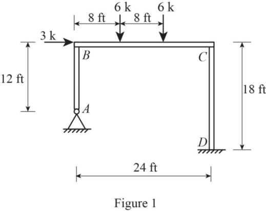
Analyze the structure calculate the horizontal displacement of joint B.
Explanation of Solution
Given information:
The Young’s modulus E is constant and equals to
Calculation:
Sketch the free body diagram of frame as shown in Figure 1.
Find the stiffness of each member connected to joint B as follows;
Find the total stiffness at joint B as follows;
Find the stiffness of each member connected to joint C as follows;
Find the total stiffness at joint C as follows;
Find the distribution factors at joint B using the relation;
Find the distribution factors at joint C using the relation;
Refer the appendix Table A.4 to find the fixed end moments.
Find the fixed end moment at each end of the member BC as follows;
| Joint | A | B | C | D | ||
| Member | AB | BA | BC | CB | CD | DC |
| DF | 0.43 | 0.57 | 0.55 | 0.45 | ||
| FEM | -32 | 32 | ||||
| Balancing | 13.76 | 18.24 | -17.6 | -14.4 | ||
| CO | -8.8 | 9.12 | -7.2 | |||
| Balancing | 3.78 | 5.02 | -5.02 | -4.1 | ||
| CO | -2.51 | 2.51 | -2.1 | |||
| Balancing | 1.08 | 1.43 | -1.38 | -1.13 | ||
| CO | -0.69 | 0.72 | -0.57 | |||
| Balancing | 0.3 | 0.39 | -0.4 | -0.32 | ||
| CO | -0.2 | 0.2 | -0.16 | |||
| Balancing | 0.09 | 0.11 | -0.11 | -0.09 | ||
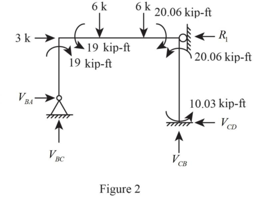
| 19 | -19 | 20.06 | -20.06 | -10.03 | ||
Sketch the free body diagram as shown in Figure 2.
Show the members AB, BC, and CD as in Figure 3.
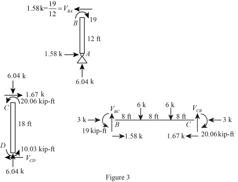
Taking moment about B ,
Summation of vertical force is equal to zero.
Taking moment about A ,
Taking moment about D,
Summation of horizontal force is equal to zero.
Find the fixed end moment at each end of the member AB as follows;
Consider the
Find the fixed end moment at each end of the member CD as follows;
| Joint | A | B | C | D | ||
| Member | AB | BA | BC | CB | CD | DC |
| DF | 0.43 | 0.57 | 0.55 | 0.45 | ||
| FEM | -86.8 | -86.8 | -48.22 | -48.22 | ||
| Balancing | 86.8 | 37.32 | 49.48 | 26.52 | 21.7 | |
| CO | 43.4 | 13.26 | 24.74 | 10.85 | ||
| Balancing | -24.36 | -32.3 | -13.61 | -11.13 | ||
| CO | -6.81 | -16.15 | -5.57 | |||
| Balancing | 2.93 | 3.88 | 8.88 | 7.27 | ||
| CO | 4.44 | 1.94 | 3.64 | |||
| Balancing | -1.91 | -2.53 | -1.07 | -0.87 | ||
| CO | -0.54 | -1.27 | -0.44 | |||
| Balancing | 0.23 | 0.31 | 0.7 | 0.57 | ||
| CO | 0.35 | 0.16 | 0.29 | |||
| Balancing | -0.15 | -0.2 | -0.09 | -0.06 | ||
| CO | -0.05 | -0.1 | -0.03 | |||
| Balancing | 0.02 | 0.03 | 0.06 | 0.04 | ||
| 0 | -29.32 | 29.32 | 30.75 | -30.75 | -39.98 | |
Show the member AB,BC, CD, as shown in figure 4.
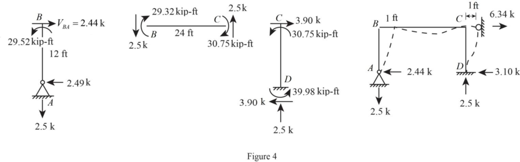
Consider span AB:
Take moment about B is Equal to zero.
Summation of forces along x-direction is Equal to zero.
Consider span BC:
Take moment about B is Equal to zero.
Summation of forces along y-direction is Equal to zero.
Consider span CD.
Take moment about C is Equal to zero.
Summation of forces along x-direction is Equal to zero.
Consider the entire structure.
Summation of forces along x-direction is Equal to zero.
Take moment about A is Equal to zero.
Summation of forces along y-direction is Equal to zero.
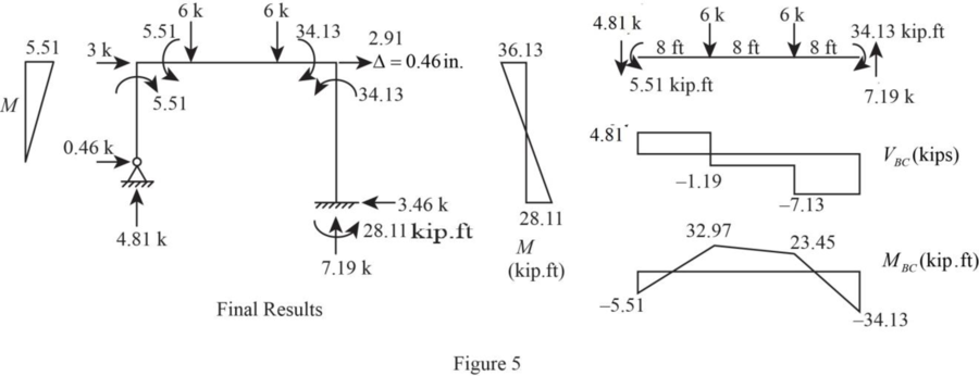
Sketch the free body diagram of shear and moment as shown in Figure 5.
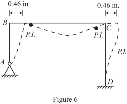
Sketch the deflected shape as shown in Figure 6.
Want to see more full solutions like this?
Chapter 11 Solutions
Fundamentals Of Structural Analysis:

- I need detailed help solving this exercise from homework of Engineering Mathematics II.I do not really understand how to do, please do it step by step, not that long but clear. Thank you!P.S.: Please do not use AI, thanks!arrow_forwardI need detailed help solving this exercise from homework of Engineering Mathematics II.I do not really understand how to do, please do it step by step, not that long but clear. Thank you!P.S.: Please do not use AI, thanks!arrow_forwarda) For the truss shown in Fig 2, determine the stiffness matrices of elements 2, 3 and 4 in the in the global co-ordinate system. Assume for each member A = 0.0015 m2 and E = 200 GPa. Indicate the degrees-of freedom in all the stiffness matrices. b) Determine the stiffness matrix of the whole truss in the global co-ordinate system. Clearly indicate the degrees-of freedom numbers in the stiffness matrix. c) Calculate all the nodal displacements and all the member forces of the truss.arrow_forward
- I want an answer very quickly, pleasearrow_forwardI want an answer very quickly, pleasearrow_forwardQ1/ Choose the correct answer for the following: 1- Cantilever retaining walls is suitable for retaining backfill about a- 8m d-4m b- 12m c- 2m e- Any height 2-The shear key is provided to a- Avoid friction behind the wall d- All of the above b- Improve appearance e- None of the above c- Increase passive resistance types of retaining wall may b- Semi-gravity retaining walls d-Counterfort retaining walls be classified as follows: 3- The common a- Gravity retaining walls walls c- Cantilever retaining e- All the mentioned 4-Related to Stability of RW, Which of the following does not represent a potential failure mode for a retaining wall? a-Bearing capacity failure of the foundation soil. b- Wall cracking due to thermal expansion. c- Excessive settlement due to weak soil layer. d- Shear failure within the foundation soil adjacent to the wall. e-Sliding along the base due to insufficient friction. 5- If the desired factor of safety against sliding is not met, which strategy is NOT a…arrow_forward
- For the truss shown in Fig 2, determine the nodal displacement and member forces using the stifness method for all elements of the truss. Assume for each member A = 0.0015 m2 and E = 200 GPa please show all workingarrow_forwardTwo W14x38 tension members are connected with a splice connection using plates attached atthe top and the bottom flanges. The design axial load Pu is 320 kips. The bolts are made of A325X, and thebolt diameter is ½ inch. (Slip-Critical connection)( LRFD units)( Previous Solution was incomplete/incorrect)arrow_forwardA tension member made of L4x4x1/2 is connected to gusset plate with welds. Using E70electrode and ½ inch weld size, design the balanced weld lengths.( Use AISC manual, LRFD units)(Previous solution was incorrect)arrow_forward

 Structural Analysis (10th Edition)Civil EngineeringISBN:9780134610672Author:Russell C. HibbelerPublisher:PEARSON
 Principles of Foundation Engineering (MindTap Cou...Civil EngineeringISBN:9781337705028Author:Braja M. Das, Nagaratnam SivakuganPublisher:Cengage Learning
 Fundamentals of Structural AnalysisCivil EngineeringISBN:9780073398006Author:Kenneth M. Leet Emeritus, Chia-Ming Uang, Joel LanningPublisher:McGraw-Hill Education
 Traffic and Highway EngineeringCivil EngineeringISBN:9781305156241Author:Garber, Nicholas J.Publisher:Cengage Learning