
Concept explainers
Videos
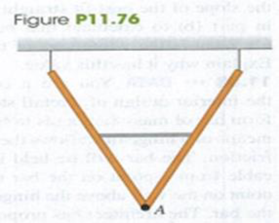
Two identical, uniform beams weighing 260 N each are connected at one end by a frictionless hinge. A light horizontal crossbar attached at the midpoints of the beams maintains an angle of 53.0° between the beams. The beams are suspended from the ceiling by vertical wires such that they form a “V” (Fig. P11.76). (a) What force does the crossbar exert on each beam? (b) Is the crossbar under tension or compression? (c) What force (magnitude and direction) does the hinge at point A exert on each beam?
Want to see the full answer?
Check out a sample textbook solution
Chapter 11 Solutions
University Physics (14th Edition)
Additional Science Textbook Solutions
Essential University Physics: Volume 1 (3rd Edition)
Applied Physics (11th Edition)
Conceptual Integrated Science
Physics for Scientists and Engineers: A Strategic Approach, Vol. 1 (Chs 1-21) (4th Edition)
Physics for Scientists and Engineers with Modern Physics


- A 10.0-kg monkey climbs a uniform ladder with weight 1.20 102 N and length L = 3.00 m as shown in Figure P12.14. The ladder rests against the wall and makes an angle of = 60.0 with the ground. The upper and lower ends of the ladder rest on frictionless surfaces. The lower end is connected to the wall by a horizontal rope that is frayed and can support a maximum tension of only 80.0 N. (a) Draw a force diagram for the ladder. (b) Find the normal force exerted on the bottom of the ladder. (c) Find the tension in the rope when the monkey is two-thirds of the way up the ladder. (d) Find the maximum distance d that the monkey can climb up the ladder before the rope breaks. (e) If the horizontal surface were rough and the rope were removed, how would your analysis of the problem change? What other information would you need to answer parts (c) and (d)? Figure P12.14arrow_forwardA stepladder of negligible weight is constructed as shown in Figure P12.40, with AC = BC = = 4.00 m. A painter of mass m = 70.0 kg stands on the ladder d = 3.00 m from the bottom. Assuming the floor is frictionless, find (a) the tension in the horizontal bar DE connecting the two halves of the ladder, (b) the normal forces at A and B, and (c) the components of the reaction force at the single hinge C that the left half of the ladder exerts on the right half. Suggestion: Treat the ladder as a single object, but also treat each half of the ladder separately. Figure P12.40 Problems 40 and 41.arrow_forwardA stepladder of negligible weight is constructed as shown in Figure P10.73, with AC = BC = = 4.00 m. A painter of mass m = 70.0 kg stands on the ladder d = 3.00 m from the bottom. Assuming the floor is frictionless, find (a) the tension in the horizontal bar DE connecting the two halves of the ladder, (b) the normal forces at A and B, and (c) the components of the reaction force at the single hinge C that the left half of the ladder exerts on the right half. Suggestion: Treat the ladder as a single object, but also treat each half of the ladder separately.arrow_forward
- A bridge of length 50.0 m and mass 8.00 104 kg is supported on a smooth pier at each end as shown in Figure P12.25. A truck of mass 3.00 104 kg is located 15.0 m from one end. What are the forces on the bridge at the points of support? Figure P12.25arrow_forwardAt a museum, a 1300-kg model aircraft is hung from a lightweight beam of length 12.0 m that is free to pivot about its base and is supported by a massless cable (Fig. P14.38). Ignore the mass of the beam. a. What is the tension in the section of the cable between the beam and the wall? b. What are the horizontal and vertical forces that the pivot exerts on the beam? FIGURE P14.38 (a) From the free-body diagram, the angle that the string tension makes with the beam is = 55.0 + 18.0 = 73.0, and the perpendicular component of the string tension is FT sin73.0. Summing torques around the base of the rod gives (Eq. 14.2): =0:(12.0m)(1300kg)(9.81m/s2)cos55.0+FT(12.0m)sin73.0=0FT=(12.0m)(1300kg)(9.81m/s2)cos55.0(12.0m)sin73.0FT=7.65103N Figure P14.38ANS (b) Using force balance (Eq. 14.1): Fx=0:FHFTcos18.0=0FH=FTcos18.0=[(12.0m)(1300kg)(9.81m/s2)cos55.0(12.0m)sin73.0]cos18.0=7.27103NFy=0:FVFTsin18.0(1300kg)(9.81m/s2)=0 FV=FTsin18.0+(1300kg)gFV=[(12.0m)(1300kg)(9.81m/s2)cos55.0(12.0m)sin73.0]sin18.0+(1300kg)(9.81m/s2)FV=1.51104Narrow_forwardA stepladder of negligible weight is constructed as shown in Figure P10.73, with AC = BC = ℓ. A painter of mass m stands on the ladder a distance d from the bottom. Assuming the floor is frictionless, find (a) the tension in the horizontal bar DE connecting the two halves of the ladder, (b) the normal forces at A and B, and (c) the components of the reaction force at the single hinge C that the left half of the ladder exerts on the right half. Suggestion: Treat the ladder as a single object, but also treat each half of the ladder separately. Figure P10.73 Problems 73 and 74.arrow_forward
- A massless, horizontal beam of length L and a massless rope support a sign of mass m (Fig. P14.78). a. What is the tension in the rope? b. In terms of m, g, d, L, and , what are the components of the force exerted by the beam on the wall? FIGURE P14.78arrow_forwardA wooden door 2.1 m high and 0.90 m wide is hung by two hinges 1.8 m apart. The lower hinge is 15 cm above the bottom of the door. The center of mass of the door is at its geometric center, and the weight of the door is 260 N, which is supported equally by both hinges. Find the horizontal force exerted by each hinge on the door.arrow_forwardA 5.45-N beam of uniform density is 1.60 m long. The beam is supported at an angle of 35.0 by a cable attached to one end. There is a pin through the other end of the beam (Fig. P14.30). Use the values given in the figure to find the tension in the cable. FIGURE P14.30arrow_forward
- In Example 14.3, we found that one of the steel cables supporting an airplane at the Udvar-Hazy Center was under a tension of 9.30 103 N. Assume the cable has a diameter of 2.30 era and an initial length of 8.00 m before the plane is suspended on the cable. How much longer is the cable when the plane is suspended on it?arrow_forwardA 215-kg robotic arm at an assembly plant is extended horizontally (Fig. P14.32). The massless support rope attached at point B makes an angle of 15.0 with the horizontal, and the center of mass of the arm is at point C. a. What is the tension in the support rope? b. What are the magnitude and direction of the force exerted by the hinge A on the robotic arm to keep the arm in the horizontal position? FIGURE P14.32arrow_forwardA flexible chain weighing 40.0 N hangs between two hooks located at the same height (Fig. P12.9). At each hook, the tangent to the chain makes an angle = 42.0 with the horizontal. Find (a) the magnitude of the force each hook exerts on the chain and (b) the tension in the chain at its midpoint. Suggestion: For part (b), make a force diagram for half of the chain. Figure P12.9arrow_forward
 Principles of Physics: A Calculus-Based TextPhysicsISBN:9781133104261Author:Raymond A. Serway, John W. JewettPublisher:Cengage Learning
 Physics for Scientists and Engineers with Modern ...PhysicsISBN:9781337553292Author:Raymond A. Serway, John W. JewettPublisher:Cengage Learning
 Physics for Scientists and EngineersPhysicsISBN:9781337553278Author:Raymond A. Serway, John W. JewettPublisher:Cengage Learning
 College PhysicsPhysicsISBN:9781285737027Author:Raymond A. Serway, Chris VuillePublisher:Cengage Learning
 Physics for Scientists and Engineers: Foundations...PhysicsISBN:9781133939146Author:Katz, Debora M.Publisher:Cengage Learning
 College PhysicsPhysicsISBN:9781305952300Author:Raymond A. Serway, Chris VuillePublisher:Cengage Learning