
Loose Leaf for Engineering Circuit Analysis Format: Loose-leaf
9th Edition
ISBN: 9781259989452
Author: Hayt
Publisher: Mcgraw Hill Publishers
expand_more
expand_more
format_list_bulleted
Videos
Textbook Question
Chapter 10.5, Problem 9P
With reference to the network shown in Fig. 10.19, find the input impedance Zin that would be measured between terminals: (a) a and g; (b) b and g; (c) a and b.
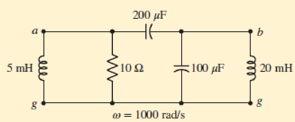
■ FIGURE 10.19
Expert Solution & Answer
Want to see the full answer?
Check out a sample textbook solution
Students have asked these similar questions
4v+9v+8v=-3v+6v',-5v,
where vi and vo are the input and output voltage, respectively.
I decided to focus on the magnitude where I do the normalization on low and high pass and have the bandpass as dB(dB(decibel), with frequency cutoff, I manage to get accurate but have trouble controlling the frequency cutoff accurately and the bandbass isn't working properly. As such I need help.My Code:
% Define frequency range for the plot
f = logspace(1, 5, 500); % Frequency range from 10 Hz to 100 kHz
w = 2 * pi * f; % Angular frequency
% Parameters for the filters
R = 1e3; % Resistance in ohms (1 kΩ)
C = 1e-6; % Capacitance in farads (1 μF)
L = 10e-3; % Inductance in henries (10 mH)
% Transfer functions
H_low = 1 ./ (1 + 1i * w * R * C); % Low-pass filter
H_high = (1i * w * R * C) ./ (1 + 1i * w * R * C); % High-pass filter
H_band = (1i * w * R * C) ./ (1 + 1i * w * L / R + 1i * w * R * C); % Band-pass filter
% Cutoff frequency for RC filters (Low-pass and High-pass)
f_cutoff_RC = 1 / (2 * pi * R * C);
% Band-pass filter cutoff frequencies
f_lower_cutoff = 1 / (2 * pi *…
Please do NOT answer if you are going to use AI. Please give a proper solution.
Chapter 10 Solutions
Loose Leaf for Engineering Circuit Analysis Format: Loose-leaf
Ch. 10.1 - Find the angle by which i1 lags v1 if v1 = 120...Ch. 10.2 - Determine values for A, B, C, and if 40 cos(100t ...Ch. 10.2 - Let vs = 40 cos 8000t V in the circuit of Fig....Ch. 10.3 - Prob. 4PCh. 10.3 - If the use of the passive sign convention is...Ch. 10.4 - Let = 2000 rad/s and t = 1 ms. Find the...Ch. 10.4 - Transform each of the following functions of time...Ch. 10.4 - In the circuit of Fig. 10.17, both sources operate...Ch. 10.5 - With reference to the network shown in Fig. 10.19,...Ch. 10.5 - In the frequency-domain circuit of Fig. 10.21,...
Ch. 10.5 - Determine the admittance (in rectangular form) of...Ch. 10.6 - Use nodal analysis on the circuit of Fig. 10.23 to...Ch. 10.6 - Use mesh analysis on the circuit of Fig. 10.25 to...Ch. 10.7 - If superposition is used on the circuit of Fig....Ch. 10.7 - Prob. 15PCh. 10.7 - Determine the current i through the 4 resistor of...Ch. 10.8 - Select some convenient reference value for IC in...Ch. 10 - Evaluate the following: (a) 5 sin (5t 9) at t =...Ch. 10 - (a) Express each of the following as a single...Ch. 10 - Prob. 3ECh. 10 - Prob. 4ECh. 10 - Prob. 5ECh. 10 - Calculate the first three instants in time (t 0)...Ch. 10 - (a) Determine the first two instants in time (t ...Ch. 10 - The concept of Fourier series is a powerful means...Ch. 10 - Household electrical voltages are typically quoted...Ch. 10 - Prob. 10ECh. 10 - Assuming there are no longer any transients...Ch. 10 - Calculate the power dissipated in the 2 resistor...Ch. 10 - Prob. 13ECh. 10 - Prob. 14ECh. 10 - Prob. 15ECh. 10 - Express the following complex numbers in...Ch. 10 - Prob. 17ECh. 10 - Prob. 18ECh. 10 - Evaluate the following, and express your answer in...Ch. 10 - Perform the indicated operations, and express the...Ch. 10 - Insert an appropriate complex source into the...Ch. 10 - For the circuit of Fig. 10.51, if is = 2 cos 5t A,...Ch. 10 - In the circuit depicted in Fig. 10.51, if is is...Ch. 10 - Employ a suitable complex source to determine the...Ch. 10 - Transform each of the following into phasor form:...Ch. 10 - Prob. 26ECh. 10 - Prob. 27ECh. 10 - The following complex voltages are written in a...Ch. 10 - Assuming an operating frequency of 50 Hz, compute...Ch. 10 - Prob. 30ECh. 10 - Prob. 31ECh. 10 - Prob. 32ECh. 10 - Assuming the passive sign convention and an...Ch. 10 - The circuit of Fig. 10.53 is shown represented in...Ch. 10 - (a) Obtain an expression for the equivalent...Ch. 10 - Determine the equivalent impedance of the...Ch. 10 - (a) Obtain an expression for the equivalent...Ch. 10 - Determine the equivalent admittance of the...Ch. 10 - Prob. 40ECh. 10 - Prob. 41ECh. 10 - Find V in Fig. 10.55 if the box contains (a) 3 in...Ch. 10 - Prob. 43ECh. 10 - Prob. 44ECh. 10 - Design a suitable combination of resistors,...Ch. 10 - Design a suitable combination of resistors,...Ch. 10 - For the circuit depicted in Fig. 10.58, (a) redraw...Ch. 10 - For the circuit illustrated in Fig. 10.59, (a)...Ch. 10 - Referring to the circuit of Fig. 10.59, employ...Ch. 10 - In the phasor-domain circuit represented by Fig....Ch. 10 - With regard to the two-mesh phasor-domain circuit...Ch. 10 - Employ phasor analysis techniques to obtain...Ch. 10 - Determine IB in the circuit of Fig. 10.62 if and ....Ch. 10 - Determine V2 in the circuit of Fig. 10.62 if and ....Ch. 10 - Employ phasor analysis to obtain an expression for...Ch. 10 - Determine the current ix in the circuit of Fig....Ch. 10 - Obtain an expression for each of the four...Ch. 10 - Determine the nodal voltages for the circuit of...Ch. 10 - Prob. 59ECh. 10 - Obtain an expression for each of the four mesh...Ch. 10 - Determine the individual contribution each current...Ch. 10 - Determine V1 and V2 in Fig. 10.68 if I1 = 333 mA...Ch. 10 - Prob. 63ECh. 10 - Obtain the Thvenin equivalent seen by the (2 j) ...Ch. 10 - The (2 j) impedance in the circuit of Fig. 10.69...Ch. 10 - With regard to the circuit depicted in Fig. 10.70,...Ch. 10 - Prob. 67ECh. 10 - Determine the individual contribution of each...Ch. 10 - Determine the power dissipated by the 1 resistor...Ch. 10 - The source Is in the circuit of Fig. 10.75 is...Ch. 10 - Prob. 72ECh. 10 - (a) Calculate values for IL, IR, IC, VL, VR, and...Ch. 10 - In the circuit of Fig. 10.77, (a) find values for...Ch. 10 - The voltage source Vs in Fig. 10.78 is chosen such...Ch. 10 - For the circuit shown in Fig. 10.79, (a) draw the...Ch. 10 - For the circuit shown in Fig. 10.80, (a) draw the...Ch. 10 - (a) Replace the inductor in the circuit of Fig....Ch. 10 - Design a purely passive network (containing only...
Knowledge Booster


Learn more about
Need a deep-dive on the concept behind this application? Look no further. Learn more about this topic, electrical-engineering and related others by exploring similar questions and additional content below.Similar questions
- P7.2 The capacitors in the circuit shown below have no energy stored in them and then switch "A" closes at time t=0. Switch "B" closes 2.5 milliseconds later. Find v(t) across the 6 μF capacitor for t≥ 0. 500 Ω B 4 µF 20 V 6 µF 7 Σ2 ΚΩ 25 mA + · μεarrow_forwardQ1: If x[n] is a discrete signal and represented by the following equation, what is the value of x[0] and X[-2] Q2: {x[n]}={-0.2,2.2,1.1,0.2,-3.7,2.9,...} a- Assuming that a 5-bit ADC channel accepts analog input ranging from 0 to 4 volts, determine the following: 1- number of quantization levels; 2-step size of the quantizer or resolution; 3- quantization level when the analog voltage is 1.28 volts. 4- binary code produced by the ADC. 5- quantization error. b- Determine whether the linear system is time invariant or not? 1 1 y(n) = x(n) Q3: Evaluate the digital convolution of the following signals using Graphical method. Find: y(0) to y(3) Q4: 2, k = 0,1,2 2, k = 0 h(k) 0 1, k = 3,4 and x(k) elsewhere = 1, k = 1,2 0 elsewhere The temperature (in Kelvin) of an electronic component can be modelled using the following approximation: T(t) [293+15e-Ju(t) A digital thermometer is used to periodically record the component's temperature, taking a sample every 5 seconds. 1- Represent the…arrow_forwardI need solution by hand clearlyarrow_forward
- fin D Q Point 7.57 in Matlab Aarrow_forwardFor the following graphical figure, write the function x(n) and h(n) in: 1. sequential vector 2. functional representation 3. Tabular 2 h0) 32 If signal x(n)-(32130 104032)], describe this signal using: 1. Graphical representation 2. Tabular representation 3. Write its expression 4. Write it as equation 5. Draw it as y(n) - x(n) u(n-3) 6. Sketch it if it is bounded at -2arrow_forwardFor the following Split-phase Manchester waveform, extract the original binary data. Then draw the AMI code for that data. 0arrow_forward1 ΚΩ N₁ m ZL (10+j4) ks2 178/0° V N2 -202 Ω Figure P11.31 Circuit for Problem 11.31.arrow_forwardCari induktasi saluran transmisi terhadapku GMDarrow_forwardA wattmeter is connected with the positive lead on phase “a” of a three-phase system. The negative lead is connected to phase “b”. A separate wattmeter has the positive lead connected to phase “c”. The negative lead of this wattmeter is connected also to phase “b”. If the input voltage is 208 volts line-to-line, the phase sequence is “abc” and the load is 1200 ohm resistors connected in “Y”, what is the expected reading of each of the wattmeters? (Hint: draw a phasor diagram)arrow_forwardarrow_back_iosSEE MORE QUESTIONSarrow_forward_ios
Recommended textbooks for you
 Delmar's Standard Textbook Of ElectricityElectrical EngineeringISBN:9781337900348Author:Stephen L. HermanPublisher:Cengage Learning
Delmar's Standard Textbook Of Electricity
Electrical Engineering
ISBN:9781337900348
Author:Stephen L. Herman
Publisher:Cengage Learning
Introduction to Two-Port Networks; Author: ALL ABOUT ELECTRONICS;https://www.youtube.com/watch?v=ru2ItcD6unI;License: Standard Youtube License