
Statics and Mechanics of Materials Plus Mastering Engineering with Pearson eText - Access Card Package (5th Edition)
5th Edition
ISBN: 9780134301006
Author: Russell C. Hibbeler
Publisher: PEARSON
expand_more
expand_more
format_list_bulleted
Concept explainers
Videos
Textbook Question
Chapter 10.5, Problem 65P
The bronze C86100 pipe has an outer diameter of 1.5 in, and a thickness of 0.125 in. The coupling on it at C is being tightened using a wrench. If the torque developed at A is 125 lb · in., determine the magnitude F of the couple forces. The pipe is fixed supported at end B.
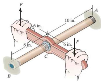
Probs. 10-65/66
Expert Solution & Answer
Want to see the full answer?
Check out a sample textbook solution
Students have asked these similar questions
For Problems 18-22 (Table 7-27), design a V-belt drive.
Specify the belt size, the sheave sizes, the number of belts, the
actual output speed, and the center distance.
only 21
only 41
Chapter 10 Solutions
Statics and Mechanics of Materials Plus Mastering Engineering with Pearson eText - Access Card Package (5th Edition)
Ch. 10.3 - Determine the internal torque at each section and...Ch. 10.3 - Determine the internal torque at each section and...Ch. 10.3 - Prob. 3PPCh. 10.3 - Prob. 4PPCh. 10.3 - Prob. 1FPCh. 10.3 - The hollow circular shaft is subjected to an...Ch. 10.3 - Prob. 3FPCh. 10.3 - Prob. 4FPCh. 10.3 - Determine the maximum shear stress in the shaft at...Ch. 10.3 - Prob. 6FP
Ch. 10.3 - The solid 50-mm-diameter shaft is subjected to the...Ch. 10.3 - Prob. 8FPCh. 10.3 - Prob. 1PCh. 10.3 - Prob. 2PCh. 10.3 - A shaft is made of an aluminum alloy having an...Ch. 10.3 - The copper pipe has an outer diameter of 40 mm and...Ch. 10.3 - The copper pipe has an outer diameter of 2.50 in....Ch. 10.3 - The solid aluminum shaft has a diameter of 50 mm...Ch. 10.3 - The solid aluminum shaft has a diameter of 50 mm....Ch. 10.3 - The solid 30-mm-diameter shaft is used to transmit...Ch. 10.3 - The solid shaft is fixed to the support at C and...Ch. 10.3 - The link acts as part of the elevator control for...Ch. 10.3 - The assembly consists of two sections of...Ch. 10.3 - The shaft has an outer diameter of 100 mm and an...Ch. 10.3 - Prob. 13PCh. 10.3 - Prob. 14PCh. 10.3 - Prob. 15PCh. 10.3 - Prob. 16PCh. 10.3 - The rod has a diameter of 1 in. and a weight of 10...Ch. 10.3 - Prob. 18PCh. 10.3 - Prob. 19PCh. 10.3 - Prob. 20PCh. 10.3 - Prob. 21PCh. 10.3 - The 60-mm-diametcr solid shaft is subjected to the...Ch. 10.3 - Prob. 23PCh. 10.3 - The 60-mm-diameter solid shaft is subjected to the...Ch. 10.3 - Prob. 25PCh. 10.3 - The pump operates using the motor that has a power...Ch. 10.3 - Prob. 27PCh. 10.3 - Prob. 28PCh. 10.3 - Prob. 29PCh. 10.3 - The gear motor can develop 2 hp when it turns at...Ch. 10.3 - Prob. 31PCh. 10.3 - The 6-hp reducer motor can turn at 1200 rev/min....Ch. 10.3 - Prob. 33PCh. 10.3 - Prob. 34PCh. 10.4 - The 60-mm-diameter steel shaft is subjected to the...Ch. 10.4 - Prob. 10FPCh. 10.4 - The hollow 6061-T6 aluminum shaft has an outer and...Ch. 10.4 - A series of gears are mounted on the...Ch. 10.4 - Prob. 13FPCh. 10.4 - The 80-mm-diameter shaft is made of steel. If it...Ch. 10.4 - The propellers of a ship are connected to an A-36...Ch. 10.4 - Prob. 36PCh. 10.4 - The splined ends and gears attached to the A992...Ch. 10.4 - Prob. 38PCh. 10.4 - The 60-mm-diameter shaft is made of 6061-T6...Ch. 10.4 - The 60-mm-diameter shaft is made of 6061-T6...Ch. 10.4 - Prob. 41PCh. 10.4 - Prob. 42PCh. 10.4 - Gear B supplies 15 kW of power, while gears A, C,...Ch. 10.4 - Prob. 44PCh. 10.4 - The turbine develops 150 kW of power, which is...Ch. 10.4 - Prob. 46PCh. 10.4 - Prob. 47PCh. 10.4 - Prob. 48PCh. 10.4 - The A 992 steel shaft has a diameter of 50 mm and...Ch. 10.4 - The turbine develops 300 kW of power, which is...Ch. 10.4 - Prob. 51PCh. 10.4 - The device shown is used to mix soils in order to...Ch. 10.4 - The 6-in.-diameter L-2 steel shaft on the turbine...Ch. 10.4 - The A-36 hollow steel shaft is 2 m long and has an...Ch. 10.4 - The A-36 solid steel shaft is 3 m long and has a...Ch. 10.4 - Prob. 56PCh. 10.4 - Prob. 57PCh. 10.4 - Prob. 58PCh. 10.4 - The tubular drive shaft for the propeller of a...Ch. 10.4 - The 60-mm diameter solid shaft is made of 2014-T6...Ch. 10.4 - Prob. 61PCh. 10.5 - The steel shaft has a diameter of 40 mm and is...Ch. 10.5 - The A992 steel shaft has a diameter of 60 mm and...Ch. 10.5 - The steel shaft is made from two segments: AC has...Ch. 10.5 - The bronze C86100 pipe has an outer diameter of...Ch. 10.5 - The bronze C86100 pipe has an outer diameter of...Ch. 10.5 - Prob. 67PCh. 10.5 - Prob. 68PCh. 10.5 - The Am1004-T61 magnesium tube is bonded to the...Ch. 10.5 - The Am1004-T61 magnesium tube is bonded to the...Ch. 10.5 - The two shafts are made of A-36 steel. Each has a...Ch. 10.5 - Prob. 72PCh. 10.5 - Prob. 73PCh. 10.5 - Prob. 74PCh. 10.5 - Prob. 75PCh. 10.5 - The composite shaft consists of a mid-section that...Ch. 10.5 - Prob. 77PCh. 10.5 - The tapered shaft is confined by the fixed...Ch. 10.5 - Prob. 79PCh. 10 - The shaft is made of A992 steel and has an...Ch. 10 - The shaft is made of A992 steel and has an...Ch. 10 - The A-36 steel circular tube is subjected to a...Ch. 10 - Prob. 4RPCh. 10 - Prob. 5RPCh. 10 - Prob. 6RPCh. 10 - Prob. 7RPCh. 10 - Prob. 8RPCh. 10 - The 60-mm-diameter shaft rotates at 300 rev/min....
Knowledge Booster


Learn more about
Need a deep-dive on the concept behind this application? Look no further. Learn more about this topic, mechanical-engineering and related others by exploring similar questions and additional content below.Similar questions
- Normal and tangential components-relate to x-y coordinates A race car enters the circular portion of a track that has a radius of 65 m. When the car enters the curve at point P, it is traveling with a speed of 120 km/h that is increasing at 5 m/s^2 . Three seconds later, determine the x and y components of velocity and acceleration of the car. I need help with finding the y component of the total acceleration. I had put -32 but its incorrect. but i keep getting figures around that numberarrow_forwardThe bracket BCD is hinged at C and attached to a control cable at B. Let F₁ = 275 N and F2 = 275 N. F1 B a=0.18 m C A 0.4 m -0.4 m- 0.24 m Determine the reaction at C. The reaction at C N Z F2 Darrow_forwardConsider the angle bar shown in the given figure A W 240 mm B 80 mm Draw the free-body diagram needed to determine the reactions at A and B when a = 150 mm. This problem could also be approached as a 3-force body using method of Section 4.2B.arrow_forward
- A telemetry system is used to quantify kinematic values of a ski jumper immediately before the jumper leaves the ramp. According to the system r=560 ft , r˙=−105 ft/s , r¨=−10 ft/s2 , θ=25° , θ˙=0.07 rad/s , θ¨=0.06 rad/s2 Determine the velocity of the skier immediately before leaving the jump. The velocity of the skier immediately before leaving the jump along with its direction is ? I have 112.08 ft/s but can't seem to get the direction correct. Determine the acceleration of the skier at this instant. At this instant, the acceleration of the skier along with its direction is ? acceleration is 22.8 ft/s^2 but need help with direction. Need help with velocity direction and acceleration direction please.arrow_forwardFor the stop bracket shown, locate the x coordinate of the center of gravity. Consider a = = 16.50 mm. 34 mm 62 mm 51 mm 10 mm 100 mm 88 mm 55 mm 45 mm The x coordinate of the center of gravity is mm.arrow_forwardIn the given figure, the bent rod ABEF is supported by bearings at C and D and by wire AH. The portion AB of the rod is 250 mm long, and the load W is 580 N. Assume that the bearing at D does not exert any axial thrust. H B A с 30° 250 mm D Z 50 mm 300 mm F 250 mm 50 mm W Draw the free-body diagram needed to determine the tension in wire AH and the reactions at C and D.arrow_forward
- A 10-ft boom is acted upon by the 810-lb force as shown in the figure. D 6 ft 6 ft E B 7 ft C 6 ft x 4 ft W Draw the free-body diagram needed to determine the tension in each cable and the reaction at the ball-and-socket joint at A.arrow_forwardLocate the center of gravity of the sheet-metal form shown. Given: r = 26.40 mm . 50 mm 40 mm X 150 mm The center of gravity (✗) of the sheet-metal form is The center of gravity (Y) of the sheet-metal form is The center of gravity ( Z ) of the sheet-metal form is mm. mm. (Round the final answer to three decimal places.) mm.arrow_forwardDetermine the reactions at the beam supports for the given loading if W = 300 lb/ft . W 6 ft A 9 ft. 6 ft- The reaction at Bis lb. The reaction at A is lb. Barrow_forward
- In the given figure, the bent rod ABEF is supported by bearings at C and D and by wire AH. The portion AB of the rod is 250 mm long, and the load W is 580 N. Assume that the bearing at D does not exert any axial thrust. 30° 250 mm 300 mm 50 mm H B C D 50 mm W 250 mm Determine the reactions at C and D. (Include a minus sign if necessary.) The reaction at Cis N) j + N)k The reaction at Dis N) j + ( N)karrow_forwardConsider the angle bar shown in the given figure A B W 240 mm- 80 mm Determine the reactions at A and B when a = 150 mm and W = 320 N. The reaction at A is N ZI The reaction at Bis N.arrow_forwardIn the given figure, the bent rod ABEF is supported by bearings at C and D and by wire AH. The portion AB of the rod is 250 mm long, and the load W is 580 N. Assume that the bearing at D does not exert any axial thrust. H B A 30° 250 mm D 300 mm 50 mm 50 mm W Determine the tension in wire AH. The tension in wire AH is N. 250 mm xarrow_forward
arrow_back_ios
SEE MORE QUESTIONS
arrow_forward_ios
Recommended textbooks for you
 International Edition---engineering Mechanics: St...Mechanical EngineeringISBN:9781305501607Author:Andrew Pytel And Jaan KiusalaasPublisher:CENGAGE L
International Edition---engineering Mechanics: St...
Mechanical Engineering
ISBN:9781305501607
Author:Andrew Pytel And Jaan Kiusalaas
Publisher:CENGAGE L
Mechanical Design (Machine Design) Clutches, Brakes and Flywheels Intro (S20 ME470 Class 15); Author: Professor Ted Diehl;https://www.youtube.com/watch?v=eMvbePrsT34;License: Standard Youtube License