
Concept explainers
Videos
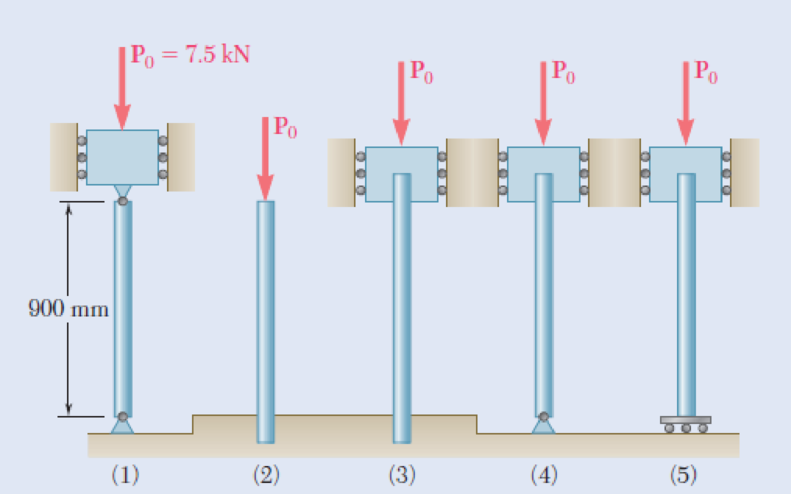
Each of the five struts shown consists of a solid steel rod. (a) Knowing that the strut of Fig. (1) is of a 20-mm diameter, determine the factor of safety with respect to buckling for the loading shown. (b) Determine the diameter of each of the other struts for which the factor of safety is the same as the factor of safety obtained in part a. Use E = 200 GPa.
Fig. P10.27
(a)
Find the factor of safety with respect to buckling.
Answer to Problem 27P
The factor of safety with respect to buckling is
Explanation of Solution
The dimeter of the strut (1) is
The centric load in the strut (1) is
The modulus of elasticity of the column is
Determine the moment of inertia of the strut (1)
Here, the diameter of the strut 1 is
Substitute 20 mm for
Both the ends are pin connected.
The effective length of the column
Determine the critical load
Here, the modulus of elasticity is E.
Substitute 200 GPa for E,
Determine the factor of safety (FOS) using the relation.
Here, the allowable load in strut 1 is
Substitute 19.14 kN for
Therefore, the factor of safety with respect to buckling is
(b)
Find the diameter of the other struts for the condition that the factor of safety is same.
Answer to Problem 27P
The diameter of the strut (2) is
The diameter of the strut (3) is
The diameter of the strut (4) is
The diameter of the strut (5) is
Explanation of Solution
Determine the factor of safety (FOS) using the relation.
Therefore, the factor of safety is directly proportional to the critical load.
Here, the moment of inertia of ith strut is
Strut (2);
Show the effective length of the strut (2) as in Figure 1.
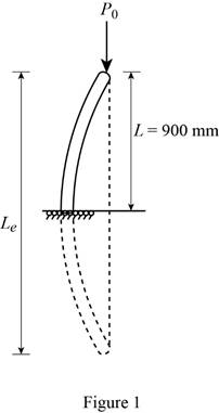
The effective length of the strut (2) is twice the length of the strut (1).
Substitute 2 for i, 2L for
Therefore, the diameter of the strut (2) is
Strut (3);
Show the effective length of the strut (3) as in Figure 2.
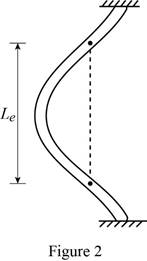
The effective length of the strut (3) is half the length of the strut (1).
Substitute 3 for i,
Therefore, the diameter of the strut (3) is
Strut (4);
Show the effective length of the strut (4) as in Figure 3.
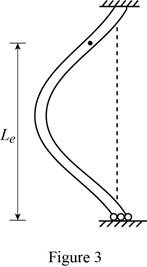
The effective length of the strut (4) is 0.7 times the length of the strut (1).
Substitute 4 for i,
Therefore, the diameter of the strut (4) is
Strut (5);
Show the effective length of the strut (5) as in Figure 4.
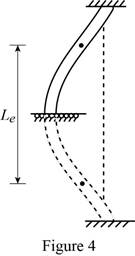
The effective length of the strut (5) is equal to the length of the strut (1).
Substitute 5 for i, L for
Therefore, the diameter of the strut (5) is
Want to see more full solutions like this?
Chapter 10 Solutions
EBK MECHANICS OF MATERIALS


- 2. A flat belt drive consists of two 4-ft diameter cast-iron pulleys spaced 16 ft apart. A power of 60 hp is transmitted by a pulley whose speed is 380 rev/min. Use a service factor (Ks) pf 1.1 and a design factor 1.0. The width of the polyamide A-3 belt is 6 in. Use CD=1. Answer the following questions. (1) What is the total length of the belt according to the given geometry? (2) Find the centrifugal force (Fc) applied to the belt. (3) What is the transmitted torque through the pulley system given 60hp? (4) Using the allowable tension, find the force (F₁) on the tight side. What is the tension at the loose side (F2) and the initial tension (F.)? (5) Using the forces, estimate the developed friction coefficient (f) (6) Based on the forces and the given rotational speed, rate the pulley set. In other words, what is the horse power that can be transmitted by the pulley system? (7) To reduce the applied tension on the tight side, the friction coefficient is increased to 0.75. Find out the…arrow_forwardThe tooth numbers for the gear train illustrated are N₂ = 24, N3 = 18, №4 = 30, №6 = 36, and N₁ = 54. Gear 7 is fixed. If shaft b is turned through 5 revolutions, how many turns will shaft a make? a 5 [6] barrow_forwardCE-112 please solve this problem step by step and give me the correct answerarrow_forward
- CE-112 please solve this problem step by step and give me the correct answerarrow_forwardCE-112 solve this problem step by step and give me the correct answer pleasearrow_forwardPlease do not use any AI tools to solve this question. I need a fully manual, step-by-step solution with clear explanations, as if it were done by a human tutor. No AI-generated responses, please.arrow_forward
- Please do not use any AI tools to solve this question. I need a fully manual, step-by-step solution with clear explanations, as if it were done by a human tutor. No AI-generated responses, please.arrow_forwardCE-112 please solve this problem step by step and give me the correct answerarrow_forwardCE-112 please solve this problem step by step and give me the correct asnwerarrow_forward
- this is an old practice exam, the answer is Ax = -4, Ay = -12,Az = 32.5, Bx= 34, Bz = 5, By = 0 but how?arrow_forwardThis is an old practice exam, the answer is Ax = Az = 0, Ay = 2000, TDE = 4750, Cx = 2000, Cy = 2000, Cz = -800 but how?arrow_forwardthis is an old practice exam, the answer is Fmin = 290.5lb but howarrow_forward
 International Edition---engineering Mechanics: St...Mechanical EngineeringISBN:9781305501607Author:Andrew Pytel And Jaan KiusalaasPublisher:CENGAGE L
 Automotive Technology: A Systems Approach (MindTa...Mechanical EngineeringISBN:9781133612315Author:Jack Erjavec, Rob ThompsonPublisher:Cengage Learning
 Mechanics of Materials (MindTap Course List)Mechanical EngineeringISBN:9781337093347Author:Barry J. Goodno, James M. GerePublisher:Cengage Learning
 Principles of Heat Transfer (Activate Learning wi...Mechanical EngineeringISBN:9781305387102Author:Kreith, Frank; Manglik, Raj M.Publisher:Cengage Learning
 Refrigeration and Air Conditioning Technology (Mi...Mechanical EngineeringISBN:9781305578296Author:John Tomczyk, Eugene Silberstein, Bill Whitman, Bill JohnsonPublisher:Cengage Learning