
Concept explainers
Videos
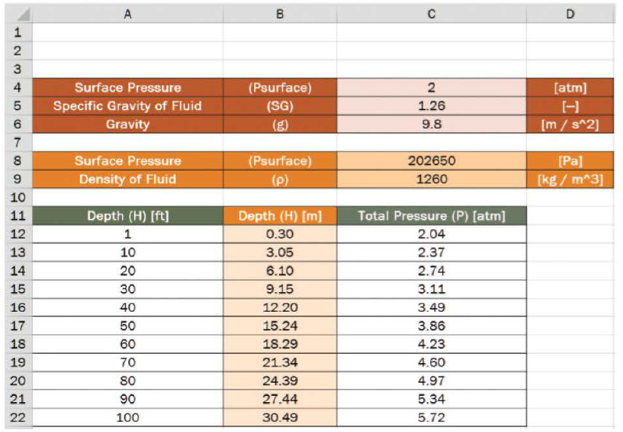
The worksheet provided was designed to calculate the total pressure felt by an object submerged in a fluid as a function of the depth to which the object is submerged.
The user will enter the surface pressure (in units of atmospheres), specific gravity of the fluid, and the gravity of the planet (in units of meters per second squared). All user input is shown in red.
The worksheet will calculate the surface pressure in units of pascals, density of the fluid in kilograms per cubic meter, and depth in units of feet. All conversions are shown in orange. Format the pressure and density to a whole number, and the height in meters to three decimal places.
Finally, the worksheet will calculate the total pressure in units of atmospheres; format to two decimal places.
 Complete the starting Excel file to meet these criteria. The following sample worksheet is shown for comparison.
Want to see the full answer?
Check out a sample textbook solution
Chapter 10 Solutions
Thinking Like an Engineer: An Active Learning Approach (3rd Edition)
Additional Engineering Textbook Solutions
Starting Out with Python (4th Edition)
Web Development and Design Foundations with HTML5 (8th Edition)
Mechanics of Materials (10th Edition)
Java How to Program, Early Objects (11th Edition) (Deitel: How to Program)
Starting Out with Programming Logic and Design (5th Edition) (What's New in Computer Science)


- CORRECT ANSWER AND COMPLETE FBD ONLY. I PREFER HANDWRITTEN BUT ITS OKAY IF NOT. I WILL UPVOTE 3. The frame has pin supports at A and E, subject to a wind load. Treat joint C to be an internal hinge. Given:Dimensions, H1 = 3.0 m; H2 = 4.5 m; L = 10.0 mWind loads, wWL (AB) = 4.8 kN/m; wWL (BC) = 3.9 kN/m; wWL (CD) = 1.5 kN/m; wWL (DE) = 1.2 kN/mMembers are made of A36 steel Wide Flange Section with the following properties:Area, A = 64000 mm2Depth, d = 762 mmFlange width, bf = 371 mmThickness of web, tw = 32 mmThickness of flange, tf = 57.9 mmMoment of inertia about x-axis, Ix = 6080 x 106 mm4The wide flange is oriented so that the bending is about the x-axis1. Calculate the stress in member AB, due to the axial load it carries, indicate if tension or compression.Answer: 0.0476 MPa Tension2. Calculate the stress in member DE, due to the axial load it carries, indicate if tension or compression.Answer: 0.2351 MPa Compression3. Calculate the maximum bending stress at B. Answer: 4.282 MPaarrow_forward32 mm 32 mm b' c' C 32 mm 32 mm b PROBLEM 6.41 a The extruded beam shown has a uniform wall thickness of 3 mm. Knowing that the vertical shear in the beam is 9 kN, determine the shearing stress at each of the five points indicated.arrow_forwardIn a structural reliability problem, the resistance (capacity) R and load effect (demand) S random variables associated with a failure mode of the structure of interest are normally distributed and statistically independent with the following probability distribution parameters (or statistics) in consistent units: MR = 12, σR = 3 μs = 5, σs = 2 (a) Determine the exact probability of failure pF ·arrow_forward
- The resistance R and load effect S for a given failure mode are statistically independent random variables with marginal PDF's 1 fR (r) = 0≤r≤100 100' fs(s)=0.05e-0.05s (a) Determine the probability of failure by computing the probability content of the failure domain defined as {rarrow_forwardPlease solve this problem as soon as possible My ID# 016948724arrow_forwardThe gears shown in the figure have a diametral pitch of 2 teeth per inch and a 20° pressure angle. The pinion rotates at 1800 rev/min clockwise and transmits 200 hp through the idler pair to gear 5 on shaft c. What forces do gears 3 and 4 transmit to the idler shaft? TS I y 18T 32T This a 12 x 18T C 48T 5arrow_forwardQuestion 1. Draw 3 teeth for the following pinion and gear respectively. The teeth should be drawn near the pressure line so that the teeth from the pinion should mesh those of the gear. Drawing scale (1:1). Either a precise hand drawing or CAD drawing is acceptable. Draw all the trajectories of the involute lines and the circles. Specification: 18tooth pinion and 30tooth gear. Diameter pitch=P=6 teeth /inch. Pressure angle:20°, 1/P for addendum (a) and 1.25/P for dedendum (b). For fillet, c=b-a.arrow_forward5. The figure shows a gear train. There is no friction at the bearings except for the gear tooth forces. The material of the milled gears is steel having a Brinell hardness of 170. The input shaft speed (n2) is 800 rpm. The face width and the contact angle for all gears are 1 in and 20° respectively. In this gear set, the endurance limit (Se) is 15 kpsi and nd (design factor) is 2. (a) Find the revolution speed of gear 5. (b) Determine whether each gear satisfies the design factor of 2.0 for bending fatigue. (c) Determine whether each gear satisfies the design factor of 2.0 for surface fatigue (contact stress). (d) According to the computation results of the questions (b) and (c), explain the possible failure mechanisms for each gear. N4=28 800rpm N₁=43 N5=34 N₂=14 P(diameteral pitch)=8 for all gears Coupled to 2.5hp motorarrow_forward1. The rotating steel shaft is simply supported by bearings at points of B and C, and is driven by a spur gear at D, which has a 6-in pitch diameter. The force F from the drive gear acts at a pressure angle of 20°. The shaft transmits a torque to point A of TA =3000 lbĘ in. The shaft is machined from steel with Sy=60kpsi and Sut=80 kpsi. (1) Draw a shear force diagram and a bending moment diagram by F. According to your analysis, where is the point of interest to evaluate the safety factor among A, B, C, and D? Describe the reason. (Hint: To find F, the torque Tд is generated by the tangential force of F (i.e. Ftangential-Fcos20°) When n=2.5, K=1.8, and K₁ =1.3, determine the diameter of the shaft based on (2) static analysis using DE theory (note that fatigue stress concentration factors need to be used for this question because the loading condition is fatigue) and (3) a fatigue analysis using modified Goodman. Note) A standard diameter is not required for the questions. 10 in Darrow_forward3 N2=28 P(diametral pitch)=8 for all gears Coupled to 25 hp motor N3=34 Full depth spur gears with pressure angle=20° N₂=2000 rpm (1) Compute the circular pitch, the center-to-center distance, and base circle radii. (2) Draw the free body diagram of gear 3 and show all the forces and the torque. (3) In mounting gears, the center-to-center distance was reduced by 0.1 inch. Calculate the new values of center-to-center distance, pressure angle, base circle radii, and pitch circle diameters. (4)What is the new tangential and radial forces for gear 3? (5) Under the new center to center distance, is the contact ratio (mc) increasing or decreasing?arrow_forward2. A flat belt drive consists of two 4-ft diameter cast-iron pulleys spaced 16 ft apart. A power of 60 hp is transmitted by a pulley whose speed is 380 rev/min. Use a service factor (Ks) pf 1.1 and a design factor 1.0. The width of the polyamide A-3 belt is 6 in. Use CD=1. Answer the following questions. (1) What is the total length of the belt according to the given geometry? (2) Find the centrifugal force (Fc) applied to the belt. (3) What is the transmitted torque through the pulley system given 60hp? (4) Using the allowable tension, find the force (F₁) on the tight side. What is the tension at the loose side (F2) and the initial tension (F.)? (5) Using the forces, estimate the developed friction coefficient (f) (6) Based on the forces and the given rotational speed, rate the pulley set. In other words, what is the horse power that can be transmitted by the pulley system? (7) To reduce the applied tension on the tight side, the friction coefficient is increased to 0.75. Find out the…arrow_forwardThe tooth numbers for the gear train illustrated are N₂ = 24, N3 = 18, №4 = 30, №6 = 36, and N₁ = 54. Gear 7 is fixed. If shaft b is turned through 5 revolutions, how many turns will shaft a make? a 5 [6] barrow_forwardarrow_back_iosSEE MORE QUESTIONSarrow_forward_ios
 International Edition---engineering Mechanics: St...Mechanical EngineeringISBN:9781305501607Author:Andrew Pytel And Jaan KiusalaasPublisher:CENGAGE L
 Welding: Principles and Applications (MindTap Cou...Mechanical EngineeringISBN:9781305494695Author:Larry JeffusPublisher:Cengage Learning
 Precision Machining Technology (MindTap Course Li...Mechanical EngineeringISBN:9781285444543Author:Peter J. Hoffman, Eric S. Hopewell, Brian JanesPublisher:Cengage Learning
 Refrigeration and Air Conditioning Technology (Mi...Mechanical EngineeringISBN:9781305578296Author:John Tomczyk, Eugene Silberstein, Bill Whitman, Bill JohnsonPublisher:Cengage Learning
 Automotive Technology: A Systems Approach (MindTa...Mechanical EngineeringISBN:9781133612315Author:Jack Erjavec, Rob ThompsonPublisher:Cengage Learning
 Principles of Heat Transfer (Activate Learning wi...Mechanical EngineeringISBN:9781305387102Author:Kreith, Frank; Manglik, Raj M.Publisher:Cengage Learning