How can liquid refrigerant be added to the refrigeration system when the system is out of refrigerant?
When the system is out of refrigerant the procedure for adding liquid refrigerant in it.
Explanation of Solution
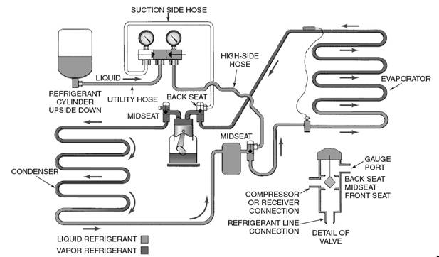
In the refrigeration system, charging a system refers to adding a refrigerant into the system. The amount and type of the charge added must be correct so that a refrigeration system can operate effectively and efficiently as it was designed to. Some refrigerant such as single-compound refrigerants may be added into the system either in the vapour or liquid states, while blended refrigerants must be charged only in the liquid state. A scale is used to determine the correct amount of refrigerant that is added to a system.
Liquid refrigerant charging of a system is normally passed in the liquid line. Liquid refrigerant can be passed into the king valve on the liquid line or receiver when a system is out of refrigerant.It moves through the evaporator and condenser. If the system is in a vacuum or has been evacuated, liquid refrigerant is allowed to enter the system until the flow has nearly stopped. After entering into the system, the liquid refrigerant will move towards the evaporator and condenser coils. While charging the system with liquid refrigerant, precautions must be taken to enter the refrigerant into the suction line of a compressor as it causes damage to the system.

Want to see more full solutions like this?
Chapter 10 Solutions
Refrigeration and Air Conditioning Technology (MindTap Course List)
- correct answer only. I will upvote.arrow_forwardCorrect answer only. I will upvote.arrow_forwardI really don't know how to approach this problem i've tried approaching it with some of the torsional stress equations I know but i'm comming up with awnsers that don't make any sence can you please help me with this?arrow_forward
- I tried this problem and don't know what I did wrong or how else I could approach it can you please help me out?arrow_forwardQ3: An engine produce 750 kW power and uses gaseous C12H26 as a fuel at 25 C; 200% theoretical air is used and air enters at 500 K. The products of combustion leave at 800 K. The heat loss from the engine is 175 kW. Determine the fuel consumption for complete combustion.arrow_forwardQu 5 Determine the carburizing time necessary to achieve a carbon concentration of 0.30 wt% at a position 4 mm into an iron carbon alloy that initially contains 0.10 wt% C. The surface concentration is to be maintained at 0.90 wt% C, and the treatment is to be conducted at 1100°C. Use the data for the diffusion of carbon into y-iron: Do = 2.3 x10⁻⁵ m2/s and Qd = 148,000 J/mol. Express your answer in hours to three significant figures. show all work step by step problems formula material sciencearrow_forward
- (Read Question)arrow_forwardIn figure A, the homogeneous rod of constant cross section is attached to unyielding supports. In figure B, a homogeneous bar with a cross-sectional area of 600 mm2 is attached to rigid supports. The bar carries the axial loads P1 = 20 kN and P2 = 60 kN, as shown.1. In figure A, derive the expression that calculates the reaction R1 in terms of P, and the given dimensions.2. In figure B, calculate the reaction (kN) at A.3. In figure B, calculate the maximum axial stress (MPa) in the rod.arrow_forward(Read image)arrow_forward
- (Read Image)arrow_forwardM16x2 grade 8.8 bolts No. 25 C1- Q.2. The figure is a cross section of a grade 25 cast-iron pressure vessel. A total of N, M16x2.0 grade 8.8 bolts are to be used to resist a separating force of 160 kN. (a) Determine ks, km, and C. (b) Find the number of bolts required for a load factor of 2 where the bolts may be reused when the joint 19 mm is taken apart. (c) with the number of bolts obtained in (b), determine the realized load factor for overload, the yielding factor of safety, and the separation factor of safety. 19 mmarrow_forwardProblem4. The thin uniform disk of mass m = 1-kg and radius R = 0.1m spins about the bent shaft OG with the angular speed w2 = 20 rad/s. At the same time, the shaft rotates about the z-axis with the angular speed 001 = 10 rad/s. The angle between the bent portion of the shaft and the z-axis is ẞ = 35°. The mass of the shaft is negligible compared to the mass of the disk. a. Find the angular momentum of the disk with respect to point G, based on the axis orientation as shown. Include an MVD in your solution. b. Find the angular momentum of the disk with respect to point O, based on the axis orientation as shown. (Note: O is NOT the center of fixed-point rotation.) c. Find the kinetic energy of the assembly. z R R 002 2R x Answer: H = -0.046ĵ-0.040 kg-m²/sec Ho=-0.146-0.015 kg-m²/sec T 0.518 N-m =arrow_forward
 Refrigeration and Air Conditioning Technology (Mi...Mechanical EngineeringISBN:9781305578296Author:John Tomczyk, Eugene Silberstein, Bill Whitman, Bill JohnsonPublisher:Cengage Learning
 Automotive Technology: A Systems Approach (MindTa...Mechanical EngineeringISBN:9781133612315Author:Jack Erjavec, Rob ThompsonPublisher:Cengage Learning

