
Concept explainers
Videos
 ICA 10-5
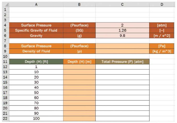
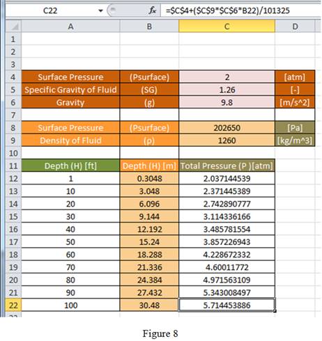
The worksheet shown here was designed to calculate the total pressure felt by an object submerged in a fluid as a function of the depth to which the object is submerged. The user will enter the surface pressure (in units of atmospheres), specific gravity of the fluid, and the gravity of the planet (in units of meters per second squared). All user input is shown in red. The worksheet will calculate the surface pressure in units of pascals, the density of the fluid in kilograms per cubic meter, and depth in units of feet. All conversions are shown in orange. Finally, the worksheet will calculate the total pressure in units of atmospheres.
- a. What formula should be typed in cell C8 to convert the surface pressure in cell C4 from atmospheres to pascals?
- b. What formula should be typed in cell C9 to determine the density in units of kilograms per cubic meter?
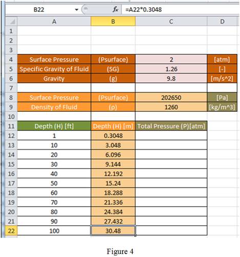
- c. What formula should be typed into cell B12 that can then be copied clown column B to convert the depth from units of feet to units of meters?
- d. What formula should be typed into cell C12 that can then be copied down column C to calculate the total pressure in units of atmospheres?
a.
Write the formula to be entered in cell C8 to convert the atmospheres surface pressure entered in cell C4 to Pascal.
Answer to Problem 1ICA
The formula to be entered in cell C8 to convert the atmospheres surface pressure entered in cell C4 to Pascal is “
Explanation of Solution
Given data:
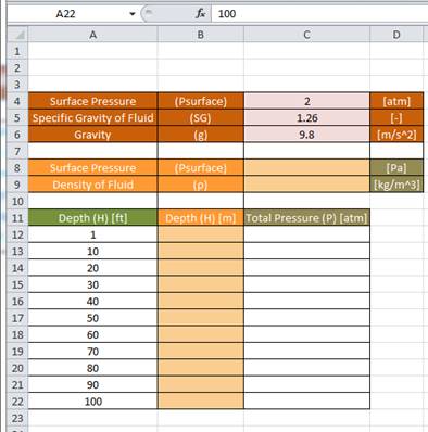
The worksheet is given as follows.
Calculation:
Consider the conversion factor for atmospheres to Pascal.
Step 1:
Using equation (1), enter the formula “
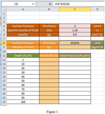
Conclusion:
Hence, the formula to be entered in cell C8 to convert the atmospheres surface pressure entered in cell C4 to Pascal is “
b.
Write the formula to be entered in cell C9 to determine the density in units of kilograms per cubic meter.
Answer to Problem 1ICA
The formula to be entered in cell C9 to determine the density in units of kilograms per cubic meter is “
Explanation of Solution
Calculation:
Write the expression for density.
Step 1:
Using equation (2), enter the formula “

Conclusion:
Hence, the formula to be entered in cell C9 to determine the density in units of kilograms per cubic meter is “
c.
Write the formula to be entered in cell B12 that can be then be copied down column B to convert the depth in feet to meters.
Answer to Problem 1ICA
The formula to be entered in cell B12 that can be then be copied down column B to convert the depth in feet to meters is “
Explanation of Solution
Calculation:
Write the conversion factor for feet to meter.
Step 1:
Using equation (3), enter the formula “
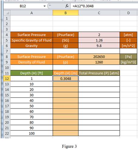
Drag the same formula for remaining cells in the column to obtain the value of depth in terms of m as shown in Figure 4.
Conclusion:
Hence, the formula to be entered in cell B12 that can be then be copied down column B to convert the depth in feet to meters is “
d.
Write the formula to be entered in cell C12 that can be then be copied down column C to calculate the total pressure in atmospheres.
Answer to Problem 1ICA
The formula to be entered in cell C12 that can be then be copied down column C to calculate the total pressure in atmospheres is “
Explanation of Solution
Calculation:
Write the expression for total pressure.
Re-arrange equation (1) as follows.
Step 1:
Since, the content of cell C8 is in Pascal, the result obtained for total pressure using cell C8, C9, C6 and B12 is divided by 101,325 to convert the result from Pascal to atmosphere.
Using equation (4) and (5), enter the formula “
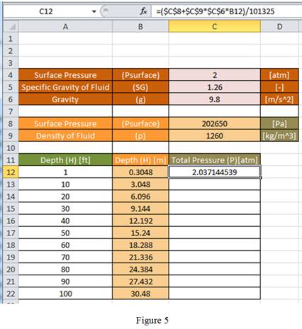
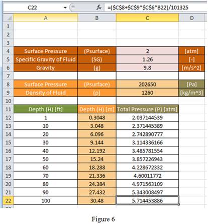
Drag the same formula for remaining cells in the column to obtain the total pressure value as shown in Figure 6.
Since, the content of cell C4 is in atmosphere, the result obtained for
Using equation (4) and (5), enter the formula “
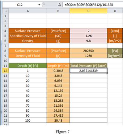
Drag the same formula for remaining cells in the column to obtain the total pressure value as shown in Figure 8.
Compare Figure 5 with Figure 7 and Figure 6 with Figure 8, the result obtained for total pressure using formula
Conclusion:
Hence, the formula to be entered in cell C12 that can be then be copied down column C to calculate the total pressure in atmospheres is “
Want to see more full solutions like this?
Chapter 10 Solutions
Thinking Like an Engineer: An Active Learning Approach (3rd Edition)
Additional Engineering Textbook Solutions
BASIC BIOMECHANICS
Automotive Technology: Principles, Diagnosis, And Service (6th Edition) (halderman Automotive Series)
Elementary Surveying: An Introduction To Geomatics (15th Edition)
Thermodynamics: An Engineering Approach
Java How to Program, Early Objects (11th Edition) (Deitel: How to Program)
Fluid Mechanics: Fundamentals and Applications


- Using AutoCADarrow_forward340 lb 340 lb Δarrow_forward4. In a table of vector differential operators, look up the expressions for V x V in a cylindrical coordinate system. (a) Compute the vorticity for the flow in a round tube where the velocity profile is = vo [1-(³] V₂ = Vo (b) Compute the vorticity for an ideal vortex where the velocity is Ve= r where constant. 2πг (c) Compute the vorticity in the vortex flow given by Ve= r 2лг 1- exp ( r² 4vt (d) Sketch all the velocity and vorticity profiles.arrow_forward
- In the figure, Neglects the heat loss and kinetic and potential energy changes, calculate the work produced by the turbine in kJ T = ??? Steam at P=3 MPa, T = 280°C Turbine Rigid tank V = 1000 m³ Turbine Rigid tank V = 100 m³ V = 1000 m³ V = 100 m³ The valve is opened. Initially: evacuated (empty) tank O a. 802.8 Initially: Closed valve O b. 572 O c. 159.93 Od. 415 e. 627.76 equilibriumarrow_forwardPlease find the torsional yield strength, the yield strength, the spring index, and the mean diameter. Use: E = 28.6 Mpsi, G = 11.5 Mpsi, A = 140 kpsi·in, m = 0.190, and relative cost= 1.arrow_forwardA viscoelastic column is made of a material with a creep compliance of D(t)= 0.75+0.5log10t+0.18(log10t)^2 GPA^-1 for t in s. If a constant compressive stress of σ0 = –100 MPa is applied at t = 0, how long will it take (= t1/2) for the height of the column to decrease to ½ its original value? Note: You will obtain multiple answers for this problem! One makes sense physically and one does not.arrow_forward
- A group of 23 power transistors, dissipating 2 W each, are to be cooled by attaching them to a black-anodized square aluminum plate and mounting the plate on the wall of a room at 30°C. The emissivity of the transistor and the plate surfaces is 0.9. Assuming the heat transfer from the back side of the plate to be negligible and the temperature of the surrounding surfaces to be the same as the air temperature of the room, determine the length of the square plate if the average surface temperature of the plate is not to exceed 50°C. Start the iteration process with an initial guess of the size of the plate as 43 cm. The properties of air at 1 atm and the film temperature of (Ts + T)/2 = (50 + 30)/2 = 40°C are k = 0.02662 W/m·°C, ν = 1.702 × 10⁻⁵ m2 /s, Pr = 0.7255, and β = 0.003195 K–1. Multiple Choice 0.473 m 0.284 m 0.513 m 0.671 marrow_forwardA 40-cm-diameter, 127-cm-high cylindrical hot water tank is located in the bathroom of a house maintained at 20°C. The surface temperature of the tank is measured to be 44°C and its emissivity is 0.4. Taking the surrounding surface temperature to be also 20°C, determine the rate of heat loss from all surfaces of the tank by natural convection and radiation. The properties of air at 32°C are k=0.02603 W/m-K, v=1.627 x 10⁻⁵ m²/s, Pr = 0.7276, and ẞ = 0.003279 K-1 The rate of heat loss from all surfaces of the tank by natural convection is The rate of heat loss from all surfaces of the tank by radiation is W. W.arrow_forwardA 2.5-m-long thin vertical plate is subjected to uniform heat flux on one side, while the other side is exposed to cool air at 5°C. The plate surface has an emissivity of 0.73, and its midpoint temperature is 55°C. Determine the heat flux subjected on the plate surface. Uniform heat flux -Plate, € = 0.73 Cool air 5°C 7 TSUIT Given: The properties of water at Tf,c= 30°C. k=0.02588 W/m.K, v=1.608 x 10⁻⁵ m²/s Pr = 0.7282 The heat flux subjected on the plate surface is W/m²arrow_forward
- Hot water is flowing at an average velocity of 5.82 ft/s through a cast iron pipe (k=30 Btu/h-ft-°F) whose inner and outer diameters are 1.0 in and 1.2 in, respectively. The pipe passes through a 50-ft-long section of a basement whose temperature is 60°F. The emissivity of the outer surface of the pipe is 0.5, and the walls of the basement are also at about 60°F. If the inlet temperature of the water is 150°F and the heat transfer coefficient on the inner surface of the pipe is 30 Btu/h-ft².°F, determine the temperature drop of water as it passes through the basement. Evaluate air properties at a film temperature of 105°C and 1 atm pressure. The properties of air at 1 atm and the film temperature of (Ts+ T∞)/2 = (150+60)/2 = 105°F are k=0.01541 Btu/h-ft-°F. v=0.1838 × 10⁻³ ft2/s, Pr = 0.7253, and ẞ = 0.00177R-1arrow_forwardhand-written solutions only, please. correct answers upvoted!arrow_forwardhand-written solutions only, please. correct answers upvoted!arrow_forward
 Elements Of ElectromagneticsMechanical EngineeringISBN:9780190698614Author:Sadiku, Matthew N. O.Publisher:Oxford University Press
 Mechanics of Materials (10th Edition)Mechanical EngineeringISBN:9780134319650Author:Russell C. HibbelerPublisher:PEARSON
 Thermodynamics: An Engineering ApproachMechanical EngineeringISBN:9781259822674Author:Yunus A. Cengel Dr., Michael A. BolesPublisher:McGraw-Hill Education
 Control Systems EngineeringMechanical EngineeringISBN:9781118170519Author:Norman S. NisePublisher:WILEY
 Mechanics of Materials (MindTap Course List)Mechanical EngineeringISBN:9781337093347Author:Barry J. Goodno, James M. GerePublisher:Cengage Learning
 Engineering Mechanics: StaticsMechanical EngineeringISBN:9781118807330Author:James L. Meriam, L. G. Kraige, J. N. BoltonPublisher:WILEY