
Concept explainers
Videos
The value of the CT secondary current (I’) and VT secondary voltage (V’).
Answer to Problem 10.1P
Explanation of Solution
Given Information:
Calculation:
The secondary voltage of the voltage transformer (V’) is,
Substitute the values in the above equation,
Now, the current (I) entering the primary of the current transformer is,
On substituting the values in the above equation,
And get,
Here, the CT equivalent circuit is,
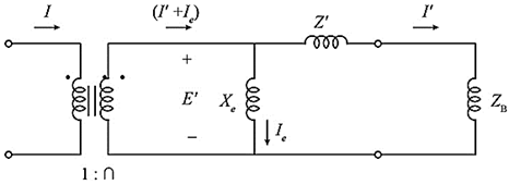
Fig: CT equivalent circuit diagram
Now, the secondary current of CT is,
Substituting the values in the above equation,
From the above equivalent circuit diagram, the secondary current consists of two components, there are
Whereas, I’ is the relay current and Ie is the exciting current.
CT error is Zero in the given question.
So that the exciting current is Zero, (Ie=0), therefore,
Want to see more full solutions like this?
Chapter 10 Solutions
POWER SYS. ANALYSIS+DESIGN


- Did you comment all methods in the Deque class to include 1. The method's behavior 2. Arguments that are passed to the method (if any), their expected types, and what they are used for 3. What the method returns (if any) 4. A description of the behavior of each line in the methodarrow_forwardWhy use a Doubly Linked List as opposed to a Singly Linked List for a Deque?arrow_forwardthis module is java 731 , follow all instructions and make sure the outputs are like what they expect and make sure the code is 100% correct . include all comments , layout and structure to be perfect too, thanks. Question 1: E-Hailing Bicycle Management System Case Study:An e-hailing company that rents out bicycles needs a system to manage its bicycles, users, and borrowing process. Each user can borrow up to 2 bicycles at a time, specifically for families with children 18 years or below. The system must track the bicycles (name, make, type, and availability) and users (name, ID, and borrowed bicycles). The company also wants to ensure that the system uses a multidimensional array to store information about the bicycles. Requirements: Add and View Bicycles: Borrow Bicycles: Return Bicycles Display Borrowed Bicycles and Search for a bicycle Create a menu-driven program to implement the above. Sample Output: Add Bicycle View All Bicycles Borrow Bicycle Return…arrow_forward
- Add a method called transfer () to the BankAccount class, that takes in an amount and destinationAccount as input and transfer the funds from current account to destination account. This method should return the balance of the current account after the transfer, also should check for the sufficient balance in current account before proceeding the transfer and if there is insufficient balance return an error message "Insufficient balance". Modify the BankAccount Test class, so that it calls the transfer () method and prints the balance after transfer. Make sure that the transfer() method updates the balance of both the current account and the destination account.arrow_forward• Create a public method called deposit() that takes in an amount of type double as input and adds the amount to the current balance. This method should also return the updated balance. • Create another public method called withdraw() that takes in an amount of type double as input, checks if the withdrawal amount is less than the current balance, and if so, subtracts the amount from the balance. If the withdrawal amount is greater than the current balance, the method should return an error message "Insufficient balance". • Create a public method getAccountInfo() that returns the account information in the format "Account Number: xxxxx, Account Holder: John Doe, Account Type: SAVINGS/CHECKING, Balance: $xxxX.XX". • Finally, create a constructor method that takes in the account number, account holder name, initial balance and account type as input and initializes the corresponding instance variables. In the BankAccount class, make sure to use the private access modifier for the instance…arrow_forwardCreate a BankAccount Test class that contains a main() method that instantiates an object of type BankAccount, with account number of 12345, account holder name of "John Doe", initial balance of $1000 and account type as SAVINGS . Then use the deposit() and withdraw() methods of the object to deposit $500 and withdraw $300. Finally, use the getAccountInfo() method to print the current account information. Use the getAccountInfo() method to verify that the deposit and withdrawal actions are performed correctly and that the account information is updated accordingly.arrow_forward
- Add a new class checkingAccount that inherits from the BankAccount class, and has a double instance variable overdraft Limit in addition to the variables inherited from the superclass. • Create a constructor for the checking Account class that takes in the account number, account holder name, initial balance, account type and overdraft limit as input, and uses the super keyword to call the constructor of the superclass, passing in the account number, account holder name and initial balance, account type. • Re-write the withdraw() method in the checkingAccount class so that it first checks if the withdrawal amount is less than the current balance plus the overdraft limit. If it is, the withdrawal is allowed and the balance is updated. If not, the method should return an error message "Insufficient funds". • Create a new method displayOverdraft Limit() that returns the overdraft limit of the CheckingAccount . • In the BankAccountTest class, create a new object of type Checking Account…arrow_forwardExplain what the rwpos() function does. What is the base case? What values are passed to the recursive call? What value is returned by the original function call?arrow_forwardExplain what the rs() function does. What value(s) does it return? Is that value always the same? Why or why not?arrow_forward
- Explain what the rwsteps() function does. What is the base case? What values are passed to the recursive call? What is printed each time rwsteps() is called? What value is returned by the original function call?arrow_forwardmodule: java Question3: (30 MARKS) Passenger Rail Agency for South Africa Train Scheduling System Problem Statement Design and implement a train scheduling system for Prasa railway network. The system should handle the following functionalities: 1. Scheduling trains: Allow the addition of train schedules, ensuring that no two trains use the same platform at the same time at any station. 2. Dynamic updates: Enable adding new train schedules and canceling existing ones. 3. Real-time simulation: Use multithreading to simulate the operation of trains (e.g., arriving, departing). 4. Data management: Use ArrayList to manage train schedules and platform assignments. Requirements 1. Add Train Schedule, Cancel Scheduled Train, View Train Schedules and Platform Management 2. Concurrency Handling with Multithreading i.e Use threads to simulate train operations, Each…arrow_forwardjava: Question 1: (40 MARKS) E-Hailing Bicycle Management System Case Study:An e-hailing company that rents out bicycles needs a system to manage its bicycles, users, and borrowing process. Each user can borrow up to 2 bicycles at a time, specifically for families with children 18 years or below. The system must track the bicycles (name, make, type, and availability) and users (name, ID, and borrowed bicycles). The company also wants to ensure that the system uses a multidimensional array to store information about the bicycles. Requirements: Add and View Bicycles: Borrow Bicycles: Return Bicycles Display Borrowed Bicycles and Search for a bicycle Create a menu-driven program to implement the above. Sample Output: Add Bicycle View All Bicycles Borrow Bicycle Return Bicycle View Borrowed Bicycles Search Bicycle ExitEnter your choice: Question 2 (30 MARKS) Pentagonal Numbers Problem Statement Create a Java program that will display the first 40 pentagonal…arrow_forward
 Operations Research : Applications and AlgorithmsComputer ScienceISBN:9780534380588Author:Wayne L. WinstonPublisher:Brooks Cole
 Systems ArchitectureComputer ScienceISBN:9781305080195Author:Stephen D. BurdPublisher:Cengage Learning
 Principles of Information Systems (MindTap Course...Computer ScienceISBN:9781285867168Author:Ralph Stair, George ReynoldsPublisher:Cengage Learning
 C++ for Engineers and ScientistsComputer ScienceISBN:9781133187844Author:Bronson, Gary J.Publisher:Course Technology Ptr
 EBK JAVA PROGRAMMINGComputer ScienceISBN:9781305480537Author:FARRELLPublisher:CENGAGE LEARNING - CONSIGNMENT
 Fundamentals of Information SystemsComputer ScienceISBN:9781337097536Author:Ralph Stair, George ReynoldsPublisher:Cengage Learning