
VECTOR MECHANICS FOR ENGINEERS: STATICS
12th Edition
ISBN: 9781259977121
Author: BEER
Publisher: MCG
expand_more
expand_more
format_list_bulleted
Videos
Textbook Question
Chapter 10, Problem 10.103RP
Determine the force P required to maintain the equilibrium of the linkage shown. All members are of the same length, and the wheels at A and B roll freely on the horizontal rod.
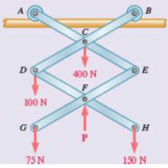
Fig. P10.103
Expert Solution & Answer
Want to see the full answer?
Check out a sample textbook solution
Students have asked these similar questions
Can you draw the left view of the first orthographic projection
Important:
I've posted this question twice and received incorrect answers. I've clearly stated that I don't require AI-generated working out. I need a genuine, expert-written solution with proper working. If you can't provide that, refer this question to someone who can please!.
Note:
Please provide a clear, step-by-step handwritten solution (no AI involvement). I require an expert-level answer and will assess it based on quality and accuracy with that I'll give it a thumbs up or down!. Hence, refer to the provided image for clarity. Double-check everything for correctness before submitting. Thank you!
Note:
Please provide a clear, step-by-step simplified handwritten working out (no explanations!), ensuring it is done without any AI involvement. I require an expert-level answer, and I will assess and rate based on the quality and accuracy of your work and refer to the provided image for more clarity. Make sure to double-check everything for correctness before submitting appreciate your time and effort!.
Question:
Chapter 10 Solutions
VECTOR MECHANICS FOR ENGINEERS: STATICS
Ch. 10.1 - Determine the vertical force P that must be...Ch. 10.1 - Determine the horizontal force P that must be...Ch. 10.1 - Prob. 10.3PCh. 10.1 - 10.3 and 10.4 Determine the couple M that must be...Ch. 10.1 - A spring of constant 15 kN/m connects points C and...Ch. 10.1 - A spring of constant 15 kN/m connects points C and...Ch. 10.1 - The two-bar linkage shown is supported by a pin...Ch. 10.1 - Determine the weight W that balances the 10-lb...Ch. 10.1 - Prob. 10.9PCh. 10.1 - Prob. 10.10P
Ch. 10.1 - Prob. 10.11PCh. 10.1 - Knowing that the line of action of the force Q...Ch. 10.1 - Solve Prob. 10.12 assuming that the force P...Ch. 10.1 - The mechanism shown is acted upon by the force P....Ch. 10.1 - Prob. 10.15PCh. 10.1 - 10.15 and 10.16 Derive an expression for the...Ch. 10.1 - A uniform rod AB with length l and weight W is...Ch. 10.1 - The pin at C is attached to member BCD and can...Ch. 10.1 - For the linkage shown, determine the couple M...Ch. 10.1 - For the linkage shown, determine the force...Ch. 10.1 - A 4-kN force P is applied as shown to the piston...Ch. 10.1 - A couple M with a magnitude of 100 Nm isapplied as...Ch. 10.1 - Rod AB is attached to a block at A that can...Ch. 10.1 - Solve Prob. 10.23, assuming that the 800-N force...Ch. 10.1 - Prob. 10.25PCh. 10.1 - Determine the value of corresponding to...Ch. 10.1 - Prob. 10.27PCh. 10.1 - Determine the value of corresponding to...Ch. 10.1 - Prob. 10.29PCh. 10.1 - Two rods AC and CE are connected by a pin at Cand...Ch. 10.1 - Solve Prob. 10.30 assuming that force P is movedto...Ch. 10.1 - Two bars AD and DG are connected by a pin at Dand...Ch. 10.1 - Solve Prob. 10.32 assuming that the 900-N...Ch. 10.1 - Two 5-kg bars AB and BC are connected by a pin atB...Ch. 10.1 - A vertical force P with a magnitude of 150 N...Ch. 10.1 - Prob. 10.36PCh. 10.1 - 10.37 and 10.38 Knowing that the constant of...Ch. 10.1 - Prob. 10.38PCh. 10.1 - The lever AB is attached to the horizontal shaft...Ch. 10.1 - Solve Prob. 10.39, assuming that P = 350 N, l =250...Ch. 10.1 - Prob. 10.41PCh. 10.1 - The position of boom ABC is controlled by...Ch. 10.1 - The position of member ABC is controlled by the...Ch. 10.1 - The position of member ABC is controlled by...Ch. 10.1 - The telescoping arm ABC is used to provide...Ch. 10.1 - Solve Prob. 10.45, assuming that the workers...Ch. 10.1 - Denoting the coefficient of static friction...Ch. 10.1 - Knowing that the coefficient of static...Ch. 10.1 - A block with weight W is pulled up a plane forming...Ch. 10.1 - Derive an expression for the mechanical...Ch. 10.1 - Denoting the coefficient of static friction...Ch. 10.1 - Knowing that the coefficient of static...Ch. 10.1 - Using the method of virtual work,...Ch. 10.1 - Using the method of virtual work, determine...Ch. 10.1 - Referring to Prob. 10.43 and using the value...Ch. 10.1 - Prob. 10.56PCh. 10.1 - Prob. 10.57PCh. 10.1 - Prob. 10.58PCh. 10.2 - Using the method of Sec. 10.2C, solve Prob. 10.29....Ch. 10.2 - Using the method of Sec. 10.2C, solve Prob. 10.30....Ch. 10.2 - Using the method of Sec. 10.2C, solve Prob. 10.31....Ch. 10.2 - Using the method of Sec. 10.2C, solve Prob. 10.32....Ch. 10.2 - Using the method of Sec. 10.2C, solve Prob. 10.34....Ch. 10.2 - Prob. 10.64PCh. 10.2 - Using the method of Sec. 10.2C, solve Prob. 10.37....Ch. 10.2 - Prob. 10.66PCh. 10.2 - Prob. 10.67PCh. 10.2 - Show that equilibrium is neutral in Prob. 10.7....Ch. 10.2 - Two uniform rods, each with a mass m, areattached...Ch. 10.2 - Two uniform rods, AB and CD, are attached to gears...Ch. 10.2 - Two uniform rods AB and CD, of the same length...Ch. 10.2 - Two uniform rods, each of mass m and length l, are...Ch. 10.2 - Using the method of Sec. 10.2C, solve Prob....Ch. 10.2 - In Prob. 10.40, determine whether each of...Ch. 10.2 - A load W of magnitude 144 lb is applied to...Ch. 10.2 - Prob. 10.76PCh. 10.2 - Prob. 10.77PCh. 10.2 - Prob. 10.78PCh. 10.2 - A slender rod AB with a weight W is attached to...Ch. 10.2 - A slender rod AB with a weight W is attached totwo...Ch. 10.2 - Prob. 10.81PCh. 10.2 - A spring AB of constant k is attached to two...Ch. 10.2 - A slender rod AB is attached to two collars A and...Ch. 10.2 - Prob. 10.84PCh. 10.2 - 10.85 and 10.86 Cart B, which weighs 75 kN, rolls...Ch. 10.2 - 10.85 and 10.86 Cart B, which weighs 75 kN, rolls...Ch. 10.2 - 10.87 and 10.88 Collar A can slide freely on the...Ch. 10.2 - 10.87 and 10.88 Collar A can slide freely on the...Ch. 10.2 - Prob. 10.89PCh. 10.2 - A vertical bar AD is attached to two springs...Ch. 10.2 - Rod AB is attached to a hinge at A and to two...Ch. 10.2 - Rod AB is attached to a hinge at A and to...Ch. 10.2 - Two bars are attached to a single spring of...Ch. 10.2 - Prob. 10.94PCh. 10.2 - The horizontal bar BEH is connected to three...Ch. 10.2 - The horizontal bar BEH is connected to three...Ch. 10.2 - Bars AB and BC, each with a length l and of...Ch. 10.2 - Prob. 10.98PCh. 10.2 - Prob. 10.99PCh. 10.2 - Prob. 10.100PCh. 10 - Determine the vertical force P that must be...Ch. 10 - Determine the couple M that must be applied...Ch. 10 - Determine the force P required to maintain...Ch. 10 - Derive an expression for the magnitude of the...Ch. 10 - Derive an expression for the magnitude of the...Ch. 10 - A vertical load W is applied to the linkage at B....Ch. 10 - A force P with a magnitude of 240 N is applied to...Ch. 10 - Two identical rods ABC and DBE are connected bya...Ch. 10 - Solve Prob. 10.108 assuming that the 24-lb load...Ch. 10 - Two uniform rods each with a mass m and length...Ch. 10 - A homogeneous hemisphere with a radius r isplaced...Ch. 10 - A homogeneous hemisphere with a radius r isplaced...
Knowledge Booster


Learn more about
Need a deep-dive on the concept behind this application? Look no further. Learn more about this topic, mechanical-engineering and related others by exploring similar questions and additional content below.Similar questions
- Note: Please provide a clear, step-by-step simplified handwritten working out (no explanations!), ensuring it is done without any AI involvement. I require an expert-level answer, and I will assess and rate based on the quality and accuracy of your work and refer to the provided image for more clarity. Make sure to double-check everything for correctness before submitting appreciate your time and effort!. Question: If the flow rate through the system below is 0.04m3s-1, find the difference in elevation H of the two reservoirs.arrow_forwardNote: Please provide a clear, step-by-step simplified handwritten working out (no explanations!), ensuring it is done without any AI involvement. I require an expert-level answer, and I will assess and rate based on the quality and accuracy of your work and refer to the provided image for more clarity. Make sure to double-check everything for correctness before submitting thanks!. Question: (In the image as provided)arrow_forwardNote: Please provide a clear, step-by-step simplified handwritten working out (no explanations!), ensuring it is done without any AI involvement. I require an expert-level answer, and I will assess and rate based on the quality and accuracy of your work and refer to the provided image for more clarity. Make sure to double-check everything for correctness before submitting thanks!. Question: The rectangular gate shown below is 3 m wide. Compute the force P needed to hold the gate in the position shown.arrow_forward
- Note: Please provide a clear, step-by-step simplified handwritten working out (no explanations!), ensuring it is done without any AI involvement. I require an expert-level answer, and I will assess and rate based on the quality and accuracy of your work and refer to the provided image for more clarity. Make sure to double-check everything for correctness before submitting thanks!. Question1: If the following container is 0.6m high, 1.2m wide and half full with water, determine the pressure acting at points A, B, and C if ax=2.6ms^-2.arrow_forwardPlease read the imagearrow_forwardChapter 12 - Lecture Notes.pptx: (MAE 272-01) (SP25) DY... Scoresarrow_forwardConsider a large 6-cm-thick stainless steel plate (k = 15.1 W/m-K) in which heat is generated uniformly at a rate of 5 × 10⁵ W/m³. Both sides of the plate are exposed to an environment at 30°C with a heat transfer coefficient of 60 W/m²K. Determine the value of the highest and lowest temperature. The highest temperature is The lowest temperature is °C. °C.arrow_forwardSketch and explain a PV Diagram and a Temperature Entropy Diagram for a 4 stroke diesel engine please, please explain into detail the difference bewteen the two and referance the a diagram. Please include a sketch or an image of each diagramarrow_forwardDraw left view of the first orthographic projectionarrow_forwardSketch and Describe a timing diagram for a 2 stroke diesel engine emphasis on the 2 stroke as my last answer explained 4 stroke please include a diagram or sketch.arrow_forwardA 4 ft 200 Ib 1000 Ib.ft C 2 ft 350 Ib - за в 2.5 ft 150 Ib 250 Ib 375 300 Ib Replace the force system acting on the frame. shown in the figure by a resultant force (magnitude and direction), and specify where its line of action intersects member (AB), measured from point (A).arrow_forwardA continuous flow calorimeter was used to obtain the calorific value of a sample of fuel and the following data collected: Mass of fuel: 2.25 kgInlet water temperature: 11 ° COutlet water temperature 60 ° CQuantity of water: 360 Liters Calorimeter efficiency: 85%Calculate the calorific value of the sample ( kJ / kg ). ive submitted this question twice and have gotten two way different answers. looking for some help thanksarrow_forwardarrow_back_iosSEE MORE QUESTIONSarrow_forward_ios
Recommended textbooks for you
 Elements Of ElectromagneticsMechanical EngineeringISBN:9780190698614Author:Sadiku, Matthew N. O.Publisher:Oxford University Press
 Mechanics of Materials (10th Edition)Mechanical EngineeringISBN:9780134319650Author:Russell C. HibbelerPublisher:PEARSON
 Thermodynamics: An Engineering ApproachMechanical EngineeringISBN:9781259822674Author:Yunus A. Cengel Dr., Michael A. BolesPublisher:McGraw-Hill Education
 Control Systems EngineeringMechanical EngineeringISBN:9781118170519Author:Norman S. NisePublisher:WILEY
 Mechanics of Materials (MindTap Course List)Mechanical EngineeringISBN:9781337093347Author:Barry J. Goodno, James M. GerePublisher:Cengage Learning
 Engineering Mechanics: StaticsMechanical EngineeringISBN:9781118807330Author:James L. Meriam, L. G. Kraige, J. N. BoltonPublisher:WILEY
Elements Of Electromagnetics
Mechanical Engineering
ISBN:9780190698614
Author:Sadiku, Matthew N. O.
Publisher:Oxford University Press
Mechanics of Materials (10th Edition)
Mechanical Engineering
ISBN:9780134319650
Author:Russell C. Hibbeler
Publisher:PEARSON
Thermodynamics: An Engineering Approach
Mechanical Engineering
ISBN:9781259822674
Author:Yunus A. Cengel Dr., Michael A. Boles
Publisher:McGraw-Hill Education
Control Systems Engineering
Mechanical Engineering
ISBN:9781118170519
Author:Norman S. Nise
Publisher:WILEY
Mechanics of Materials (MindTap Course List)
Mechanical Engineering
ISBN:9781337093347
Author:Barry J. Goodno, James M. Gere
Publisher:Cengage Learning
Engineering Mechanics: Statics
Mechanical Engineering
ISBN:9781118807330
Author:James L. Meriam, L. G. Kraige, J. N. Bolton
Publisher:WILEY
Mechanical SPRING DESIGN Strategy and Restrictions in Under 15 Minutes!; Author: Less Boring Lectures;https://www.youtube.com/watch?v=dsWQrzfQt3s;License: Standard Youtube License