
Basic Engineering Circuit Analysis
11th Edition
ISBN: 9781118992661
Author: Irwin, J. David, NELMS, R. M., 1939-
Publisher: Wiley,
expand_more
expand_more
format_list_bulleted
Concept explainers
Videos
Textbook Question
Chapter 1, Problem 30P
Choose
Expert Solution & Answer
Want to see the full answer?
Check out a sample textbook solution
Students have asked these similar questions
If Fourier transform of f(t) is F(w) find Fourier transform of g(t) using
only properties.
d
g(t) = f(2t)+8(3-1)+ ej(t-1)f(t)
dt
3z²+7z+1
dz
(b) If C is the circle |z+i|=1.
What is the value of S
(a) If C is the circle |z+1|=1.
z+1
(c) If C is the ellipse x²+y2=8.
=
Find the residues of all the poles of f(z) =
3z
(z+2)²(z²-1)
Chapter 1 Solutions
Basic Engineering Circuit Analysis
Ch. 1 - If the current in an electric conductor is 2.4 A,...Ch. 1 - Determine the time interval required for a 12�A...Ch. 1 - A lightning bolt carrying 30,000 A lasts for 50...Ch. 1 - If a 12-V battery delivers 100 J in 5 s, find (a)...Ch. 1 - The current in a conductor is 1.5 A. How many...Ch. 1 - If 60 C of charge pass through an electric...Ch. 1 - Determine the number of coulombs of charge...Ch. 1 - Five coulombs of charge pass through the element...Ch. 1 - The current that enters an element is shown in...Ch. 1 - The charge entering the positive terminal of an...
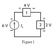
Ch. 1 - The charge entering the positive terminal of an...Ch. 1 - Prob. 12PCh. 1 - The power absorbed by the BOX in Fig. Pl. 13 is...Ch. 1 - The power absorbed by the BOX in Fig. Pl. 14 is...Ch. 1 - The energy absorbed by the BOX in Fig. P1.15 is...Ch. 1 - The charge that enters the BOX in Fig. P1.16 is...Ch. 1 - The energy absorbed by the BOX in Fig. Pl. 17 is...Ch. 1 - The charge entering the upper terminal of the BOX...Ch. 1 - The energy absorbed by the BOX in Fig. Pl. 19 is...Ch. 1 - Determine the amount of power absorbed or supplied...Ch. 1 - Calculate the power absorbed by element A in Fig....Ch. 1 - Calculate the power supplied by element A in Fig....Ch. 1 - Element A in the diagram in Fig. PI .23 absorbs 30...Ch. 1 - Element B in the diagram in Fig. P1.24 supplies 60...Ch. 1 - Element B in the diagram in Fig. PI .25 supplies...Ch. 1 - Element B in the diagram in Fig. Pl.26 supplies 72...Ch. 1 - (a) In Fig. Pl.27 (a), P1=36W. Is element 2...Ch. 1 - Two elements are connected in series, as shown in...Ch. 1 - Element 2 in Fig. Pl.29 absorbed 32W. Find the...Ch. 1 - Choose Is such that the power absorbed by element...Ch. 1 - Find the power that is absorbed or supplied by the...Ch. 1 - Find the power that is absorbed or supplied by the...Ch. 1 - Compute the power that is absorbed or supplied by...Ch. 1 - Find the power that is absorbed or supplied by...Ch. 1 - Find Ix in the network in Fig. P1.35.Ch. 1 - Prob. 36PCh. 1 - Find the power absorbed or supplied by element 1...Ch. 1 - Find the power absorbed or supplied by element 3...Ch. 1 - Find the power absorbed or supplied by element 1...Ch. 1 - Find Vx in the network in Fig. P1.40 using...Ch. 1 - Find Ix in the circuit in Fig. P1.41 using...Ch. 1 - Is the source Vs in the network in Fig. P1.42...Ch. 1 - Find I0 in the network in Fig. P1.43 using...Ch. 1 - Calculate the power absorbed by each element in...Ch. 1 - Calculate the power absorbed by each element in...Ch. 1 - In the circuit in Fig. P1.46, element 1 absorbs 40...
Knowledge Booster


Learn more about
Need a deep-dive on the concept behind this application? Look no further. Learn more about this topic, electrical-engineering and related others by exploring similar questions and additional content below.Similar questions
- find the inverse Laplace transform of X(s)= i) Re[s]> 3 ii) Re[s]<1 s+5 for (s-1)(s-2)(s-3) iii) 1arrow_forwardFor R1, what is the resistance in kΩ? For R1, what the current in mA? For R1, what is the voltage in V? For R1, what is the power in W? For R2, what is the resistance in kΩ? For R2, what the current in mA? For R2, what is the voltage in V? For R2, what is the power in W? For R3, what is the resistance in kΩ? For R3, what the current in mA? For R3, what is the voltage in V? For R3, what is the power in W? For R4, what is the resistance in kΩ? For R4, what the current in mA? For R4, what is the voltage in V? For R4, what is the power in W? For R5, what is the resistance in kΩ? For R5, what the current in mA? For R5, what is the voltage in V? For R5, what is the power in W? What is the total resistance in Ω? What is the total current in mA? What is the total voltage in V? What is the total power in W?arrow_forwardPlease answer allarrow_forwardarrow_back_iosSEE MORE QUESTIONSarrow_forward_ios
Recommended textbooks for you
 Introductory Circuit Analysis (13th Edition)Electrical EngineeringISBN:9780133923605Author:Robert L. BoylestadPublisher:PEARSON
 Delmar's Standard Textbook Of ElectricityElectrical EngineeringISBN:9781337900348Author:Stephen L. HermanPublisher:Cengage Learning
 Programmable Logic ControllersElectrical EngineeringISBN:9780073373843Author:Frank D. PetruzellaPublisher:McGraw-Hill Education
 Fundamentals of Electric CircuitsElectrical EngineeringISBN:9780078028229Author:Charles K Alexander, Matthew SadikuPublisher:McGraw-Hill Education
 Electric Circuits. (11th Edition)Electrical EngineeringISBN:9780134746968Author:James W. Nilsson, Susan RiedelPublisher:PEARSON
 Engineering ElectromagneticsElectrical EngineeringISBN:9780078028151Author:Hayt, William H. (william Hart), Jr, BUCK, John A.Publisher:Mcgraw-hill Education,
Introductory Circuit Analysis (13th Edition)
Electrical Engineering
ISBN:9780133923605
Author:Robert L. Boylestad
Publisher:PEARSON
Delmar's Standard Textbook Of Electricity
Electrical Engineering
ISBN:9781337900348
Author:Stephen L. Herman
Publisher:Cengage Learning
Programmable Logic Controllers
Electrical Engineering
ISBN:9780073373843
Author:Frank D. Petruzella
Publisher:McGraw-Hill Education
Fundamentals of Electric Circuits
Electrical Engineering
ISBN:9780078028229
Author:Charles K Alexander, Matthew Sadiku
Publisher:McGraw-Hill Education
Electric Circuits. (11th Edition)
Electrical Engineering
ISBN:9780134746968
Author:James W. Nilsson, Susan Riedel
Publisher:PEARSON
Engineering Electromagnetics
Electrical Engineering
ISBN:9780078028151
Author:Hayt, William H. (william Hart), Jr, BUCK, John A.
Publisher:Mcgraw-hill Education,
Current Divider Rule; Author: Neso Academy;https://www.youtube.com/watch?v=hRU1mKWUehY;License: Standard YouTube License, CC-BY