
Concept explainers
Videos
How does the science of heat transfer differ from the science of
The difference between science of heat transfer and science of thermodynamics.
Explanation of Solution
Heat transfer is defined as the science which deals with the rate of transfer of energy. It tells about the basic information of the amount of heat transfer at a specified instantaneous time. Transfer of heat occurs when there is difference in the temperature of the body and the surroundings. It does not achieve equilibrium stage as heat transfer is a non-equilibrium phenomenon.
Whereas,the science of thermodynamics deals with the amount of heat transfer when a system experiences state change. It does not give any information about the rate of energy transfer.
Thermodynamics system does not give any information related to the nature of the state change.Heat transfer takes place from the region of higher temperature to the region of low temperature.
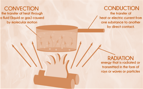
Fig.-1: Modes of heat transfer.
Want to see more full solutions like this?
Chapter 1 Solutions
HEAT+MASS TRANSFER:FUND..(LL)-W/CONNECT


- Hi, can you please help me .Identify and justify suitable analytical techniques of the scenario below, bearing in mind the kinds of information being handled to reach a conclusion (methodology). A child swing set was discovered to have failed at the fixing at the top of the chains connecting the seat to the top of the swing set. A 12 mm threaded steel bolt, connecting the shackle to the top beam, failed at the start of the threaded region on the linkage closest to the outside side of the swing set . The linkage and bolts were made of electro galvanised mild steel . The rigid bar chain alternatives and fixings were of the same material and appeared to be fitted in accordance with guidelines. The yield strength of the steel used is 260 MPa and the UTS is 380 MPa. The bolt that failed was threaded using a standard thread with a pitch (distance between threads) of 1.75 mm and a depth of approximately 1.1 mm. The swing set in question had been assigned to ‘toddlers’ with the application of…arrow_forwardHi, can you please define and calculate the failure mode of the linkage that failed on the swing (images added) : A child swing set was discovered to have failed at the fixing at the top of the chains connecting the seat to the top of the swing set. A 12 mm threaded steel bolt, connecting the shackle to the top beam, failed at the start of the threaded region on the linkage closest to the outside side of the swing set . The linkage and bolts were made of electro galvanised mild steel . The rigid bar chain alternatives and fixings were of the same material and appeared to be fitted in accordance with guidelines. The yield strength of the steel used is 260 MPa and the UTS is 380 MPa. The bolt that failed was threaded using a standard thread with a pitch (distance between threads) of 1.75 mm and a depth of approximately 1.1 mm. The swing set in question had been assigned to ‘toddlers’ with the application of a caged-type seat. However, the location was within the play area not…arrow_forwardPage 11-68. The rectangular plate shown is subjected to a uniaxial stress of 2000 psi. Compute the shear stress and the tensile developed on a plane forming an angle of 30° with the longitud axis of the member. (Hint: Assume a cross-sectional area of unity) 2000 psi 2000 psi hparrow_forward
- 11-70. A shear stress (pure shear) of 5000 psi exists on an element. (a) Determine the maximum tensile and compressive stresses caused in the element due to this shear. (b) Sketch the element showing the planes on which the maximum tensile and compressive stresses act.arrow_forward11-20. An aluminum specimen of circular cross section, 0.50 in. in diameter, ruptured under a tensile load of 12,000 lb. The plane of failure was found to be at 48° with a plane perpendicular to the longitudinal axis of the specimen. (a) Compute the shear stress on the failure plane. (b) Compute the maximum tensile stress. (c) Compute the tensile stress on the failure plane. hparrow_forwardA long flat steel bar 13 mm thick and 120 mm wide has semicircular grooves as shown and carries a tensile load of 50 kN Determine the maximum stress if plate r= 8mm r=21mm r=38mmarrow_forward
- Problem 13: F₁ = A =250 N 30% Determine the moment of each of the three forces about point B. F₂ = 300 N 60° 2 m -3 m B 4 m F3=500 Narrow_forward3 kN 3 kN 1.8 kN/m 80 mm B 300 mm D an 1.5 m-1.5 m--1.5 m- PROBLEM 5.47 Using the method of Sec. 5.2, solve Prob. 5.16 PROBLEM 5.16 For the beam and loading shown, determine the maximum normal stress due to bending on a transverse section at C.arrow_forward300 mm 3 kN 3 kN 450 N-m D E 200 mm 300 mm PROBLEM 5.12 Draw the shear and bending-moment diagrams for the beam and loading shown, and determine the maximum absolute value (a) of the shear, (b) of the bending moment.arrow_forward
- CORRECT AND DETAILED SOLUTION WITH FBD ONLY. I WILL UPVOTE THANK YOU. CORRECT ANSWER IS ALREADY PROVIDED. I REALLY NEED FBD. The cantilevered spandrel beam shown whose depth tapers from d1 to d2, has a constant width of 120mm. It carries a triangularly distributed end reaction.Given: d1 = 600 mm, d2 = 120 mm, L = 1 m, w = 100 kN/m1. Calculate the maximum flexural stress at the support, in kN-m.2. Determine the distance (m), from the free end, of the section with maximum flexural stress.3. Determine the maximum flexural stress in the beam, in MPa.ANSWERS: (1) 4.630 MPa; (2) 905.8688 m; (3) 4.65 MPaarrow_forwardCORRECT AND DETAILED SOLUTION WITH FBD ONLY. I WILL UPVOTE THANK YOU. CORRECT ANSWER IS ALREADY PROVIDED. I REALLY NEED FBD A concrete wall retains water as shown. Assume that the wall is fixed at the base. Given: H = 3 m, t = 0.5m, Concrete unit weight = 23 kN/m3Unit weight of water = 9.81 kN/m3(Hint: The pressure of water is linearly increasing from the surface to the bottom with intensity 9.81d.)1. Find the maximum compressive stress (MPa) at the base of the wall if the water reaches the top.2. If the maximum compressive stress at the base of the wall is not to exceed 0.40 MPa, what is the maximum allowable depth(m) of the water?3. If the tensile stress at the base is zero, what is the maximum allowable depth (m) of the water?ANSWERS: (1) 1.13 MPa, (2) 2.0 m, (3) 1.20 marrow_forwardCORRECT AND DETAILED SOLUTION WITH FBD ONLY. I WILL UPVOTE THANK YOU. CORRECT ANSWER IS ALREADY PROVIDED. I NEED FBD A short plate is attached to the center of the shaft as shown. The bottom of the shaft is fixed to the ground.Given: a = 75 mm, h = 125 mm, D = 38 mmP1 = 24 kN, P2 = 28 kN1. Calculate the maximum torsional stress in the shaft, in MPa.2. Calculate the maximum flexural stress in the shaft, in MPa.3. Calculate the maximum horizontal shear stress in the shaft, in MPa.ANSWERS: (1) 167.07 MPa; (2) 679.77 MPa; (3) 28.22 MPaarrow_forward
 Principles of Heat Transfer (Activate Learning wi...Mechanical EngineeringISBN:9781305387102Author:Kreith, Frank; Manglik, Raj M.Publisher:Cengage Learning