
Concept explainers
Videos
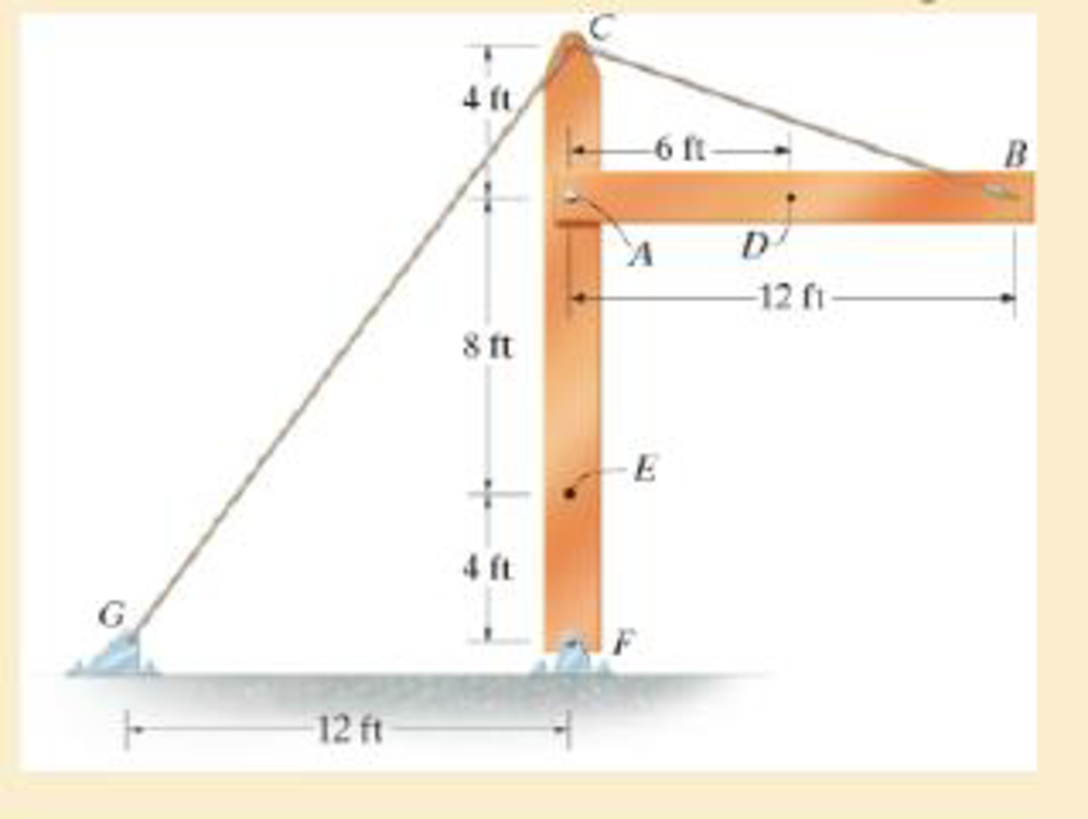
The beam AB is pin supported at A and supported by a cable BC. A separate cable CG is used to hold up the frame. If AB weighs 120 lb/ft and the column FC has a weight of 180 lb/ft, determine the resultant internal loadings acting on cross sections located at points D and E.
Answer to Problem 1.97RP
The resultant internal loadings at cross section at D are
The resultant internal loadings at cross section at E are
Explanation of Solution
Given information:
The beam AB is pin supported at A and supported by a cable BC.
The weight of the beam AB is
The weight of the column FC is
Calculation:
Find the loading at the center of the beam AB
Substitute
Convert the unit from lb to kip.
Sketch the Free Body Diagram of the beam AB shown in Figure 1.
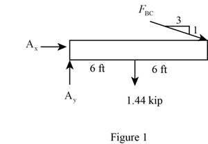
Refer to Figure 1.
Find the angle of cable BC to the horizontal
Find the tension in cable BC as shown below.
Take moment about A is Equal to zero.
Find the support reaction at A as shown below.
Apply the Equations of Equilibrium as shown below.
Summation of forces along horizontal direction is Equal to zero.
Summation of forces along vertical direction is Equal to zero.
Find the loading at the center of the beam AD
Substitute
Convert the unit from lb to kip.
Sketch the Free Body Diagram of the section for point D as shown in Figure 2.
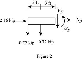
Refer to Figure 2.
Find the internal loadings as shown below.
Apply the Equations of Equilibrium as shown below.
Summation of forces along horizontal direction is Equal to zero.
Summation of forces along vertical direction is Equal to zero.
Take moment about D is Equal to zero.
Hence, the resultant internal loadings at cross section at D are
Find the loading at the center of the column FC
Substitute
Convert the unit from lb to kip.
Sketch the Free Body Diagram of the beam FC shown in Figure 3.
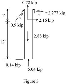
Refer to Figure 3.
Find the angle of cable CG to the horizontal.
Find the tension in cable CG as shown below.
Summation of forces along horizontal direction is Equal to zero.
Find the loading at the center of the column FE
Substitute
Convert the unit from lb to kip.
Sketch the Free Body Diagram of the section for point E as shown in Figure 4.
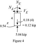
Refer to Figure 4.
Find the internal loadings as shown below.
Apply the Equations of Equilibrium as shown below.
Summation of forces along horizontal direction is Equal to zero.
Summation of forces along vertical direction is Equal to zero.
Take moment about E is Equal to zero.
Therefore, the resultant internal loadings at cross section at E are
Want to see more full solutions like this?
Chapter 1 Solutions
Mechanics of Materials
Additional Engineering Textbook Solutions
Starting Out with Java: From Control Structures through Objects (7th Edition) (What's New in Computer Science)
Degarmo's Materials And Processes In Manufacturing
Starting Out with C++: Early Objects (9th Edition)
Computer Science: An Overview (13th Edition) (What's New in Computer Science)
Introduction To Programming Using Visual Basic (11th Edition)
Starting Out with Python (4th Edition)


- Determine the magnitude of the minimum force P needed to prevent the 20 kg uniform rod AB from sliding. The contact surface at A is smooth, whereas the coefficient of static friction between the rod and the floor is μs = 0.3.arrow_forwardDetermine the magnitudes of the reactions at the fixed support at A.arrow_forwardLet Hill frame H = {i-hat_r, i-hat_θ, i-hat_h} be the orbit frame of the LMO satellite. These base vectors are generally defined as:i-hat_r = r_LM / |r_LM|, i-hat_theta = i-hat_h X i-hat_r, i-hat_h = r_LM X r-dot_LMO /( | r_LM X r-dot_LMO | ) How would you: • Determine an analytic expressions for [HN]arrow_forward
- De Moivre’s Theoremarrow_forwardhand-written solutions only, please.arrow_forwardDetermine the shear flow qqq for the given profile when the shear forces acting at the torsional center are Qy=30Q_y = 30Qy=30 kN and Qz=20Q_z = 20Qz=20 kN. Also, calculate qmaxq_{\max}qmax and τmax\tau_{\max}τmax. Given:Iy=10.5×10⁶I_y = 10.5 \times 10^6Iy=10.5×106 mm4^44,Iz=20.8×10⁶I_z = 20.8 \times 10^6Iz=20.8×106 mm4^44,Iyz=6×10⁶I_{yz} = 6 \times 10^6Iyz=6×106 mm4^44. Additional parameters:αy=0.5714\alpha_y = 0.5714αy=0.5714,αz=0.2885\alpha_z = 0.2885αz=0.2885,γ=1.1974\gamma = 1.1974γ=1.1974. (Check hint: τmax\tau_{\max}τmax should be approximately 30 MPa.)arrow_forward
- hand-written solutions only, please.arrow_forwardIn the bending of a U-profile beam, the load path passes through the torsional center C, causing a moment of 25 kNm at the cross-section under consideration. Additionally, the beam is subjected to an axial tensile force of 100 kN at the centroid. Determine the maximum absolute normal stress.(Check hint: approximately 350 MPa, but where?)arrow_forward### Make an introduction to a report of a rocket study project, in the OpenRocket software, where the project consists of the simulation of single-stage and two-stage rockets, estimating the values of the exhaust velocities of the engines used, as well as obtaining the graphs of "altitude", "mass ratio x t", "thrust x t" and "ψ × t".arrow_forward
- A 6305 ball bearing is subjected to a steady 5000-N radial load and a 2000-N thrust load and uses a very clean lubricant throughout its life. If the inner race angular velocity is 500 rpm find The equivalent radial load the L10 life and the L50 lifearrow_forwardWhere on the below beam is the Maxiumum Slope likely to occur? C A; Атят Barrow_forwardWhat is the moment of Inertia of this body? What is Ixx, Iyy, and Izzarrow_forward
 Elements Of ElectromagneticsMechanical EngineeringISBN:9780190698614Author:Sadiku, Matthew N. O.Publisher:Oxford University Press
 Mechanics of Materials (10th Edition)Mechanical EngineeringISBN:9780134319650Author:Russell C. HibbelerPublisher:PEARSON
 Thermodynamics: An Engineering ApproachMechanical EngineeringISBN:9781259822674Author:Yunus A. Cengel Dr., Michael A. BolesPublisher:McGraw-Hill Education
 Control Systems EngineeringMechanical EngineeringISBN:9781118170519Author:Norman S. NisePublisher:WILEY
 Mechanics of Materials (MindTap Course List)Mechanical EngineeringISBN:9781337093347Author:Barry J. Goodno, James M. GerePublisher:Cengage Learning
 Engineering Mechanics: StaticsMechanical EngineeringISBN:9781118807330Author:James L. Meriam, L. G. Kraige, J. N. BoltonPublisher:WILEY