ww 79.190 OV 0 mA OW +|||+ R₁ R₂ Ο Ω OV 0 mA 17.8 w Ο Ω OV O MA 18.84 W
ww 79.190 OV 0 mA OW +|||+ R₁ R₂ Ο Ω OV 0 mA 17.8 w Ο Ω OV O MA 18.84 W

Introductory Circuit Analysis (13th Edition)
13th Edition
ISBN:9780133923605
Author:Robert L. Boylestad
Publisher:Robert L. Boylestad
Chapter1: Introduction
Section: Chapter Questions
Problem 1P: Visit your local library (at school or home) and describe the extent to which it provides literature...

Related questions

Question

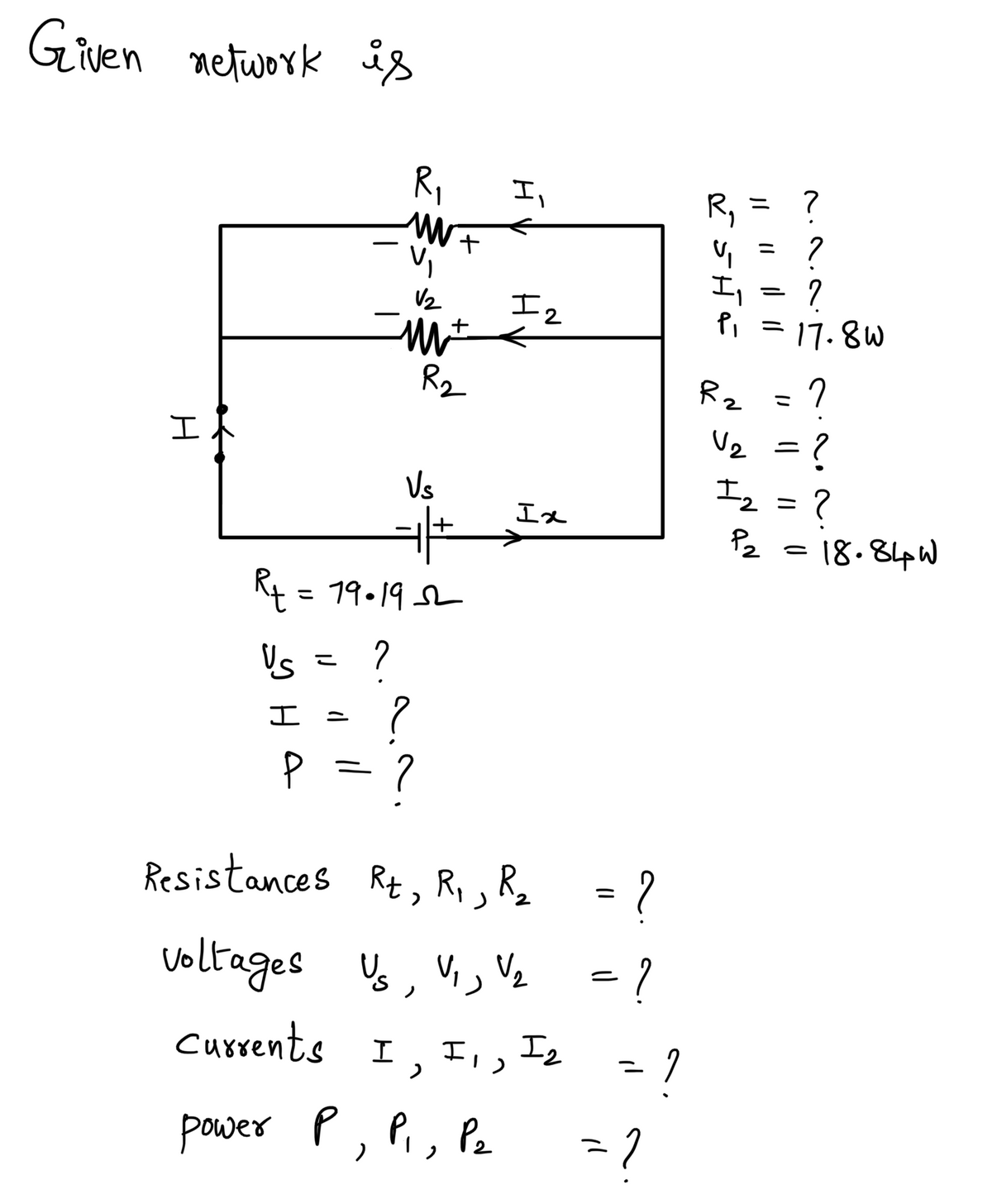
Transcribed Image Text:The image depicts a simple electrical circuit diagram featuring two resistors, \( R_1 \) and \( R_2 \), connected in parallel. Below is a detailed description suitable for an educational context:
### Circuit Components:
- **Resistors (R_1 and R_2):** These are depicted by the zigzag lines.
- **Battery:** Represented by the two parallel lines at the bottom, indicating the power source.
- **Switch:** Illustrated as a small circle connected to the wire at the left, typically used to open or close the circuit.
### Measurements and Values:
- **Resistor \( R_1 \):**
- Resistance: Not specified as an explicit value.
- Power: 17.8 W (watts) noted beside \( R_1 \).
- **Resistor \( R_2 \):**
- Resistance: Not specified as an explicit value.
- Power: 18.84 W (watts) noted beside \( R_2 \).
- **Total Circuit Resistance:**
- Measured as 79.19 Ω (ohms), displayed in a labeled box on the left.
### Observations:
- The circuit diagram layout shows that both resistors \( R_1 \) and \( R_2 \) are connected in parallel to a voltage source.
- The green markers next to the resistors indicate that power consumption is actively measured for both resistors.
- No voltage (V), current (mA), or power (W) values are filled in, other than the noted power consumption of resistors and total resistance.
This diagram is useful for understanding basic parallel circuit configurations and power distribution among resistors.
Expert Solution
Step 1: We need to determine resistances, voltages, currents and power

Trending now
This is a popular solution!

Step by step
Solved in 3 steps with 3 images

Knowledge Booster


Learn more about
Need a deep-dive on the concept behind this application? Look no further. Learn more about this topic, electrical-engineering and related others by exploring similar questions and additional content below.Recommended textbooks for you
Introductory Circuit Analysis (13th Edition)
Electrical Engineering
ISBN:
9780133923605
Author:
Robert L. Boylestad
Publisher:
PEARSON

Delmar's Standard Textbook Of Electricity
Electrical Engineering
ISBN:
9781337900348
Author:
Stephen L. Herman
Publisher:
Cengage Learning

Programmable Logic Controllers
Electrical Engineering
ISBN:
9780073373843
Author:
Frank D. Petruzella
Publisher:
McGraw-Hill Education
Introductory Circuit Analysis (13th Edition)
Electrical Engineering
ISBN:
9780133923605
Author:
Robert L. Boylestad
Publisher:
PEARSON
Delmar's Standard Textbook Of Electricity
Electrical Engineering
ISBN:
9781337900348
Author:
Stephen L. Herman
Publisher:
Cengage Learning
Programmable Logic Controllers
Electrical Engineering
ISBN:
9780073373843
Author:
Frank D. Petruzella
Publisher:
McGraw-Hill Education

Fundamentals of Electric Circuits
Electrical Engineering
ISBN:
9780078028229
Author:
Charles K Alexander, Matthew Sadiku
Publisher:
McGraw-Hill Education

Electric Circuits. (11th Edition)
Electrical Engineering
ISBN:
9780134746968
Author:
James W. Nilsson, Susan Riedel
Publisher:
PEARSON

Engineering Electromagnetics
Electrical Engineering
ISBN:
9780078028151
Author:
Hayt, William H. (william Hart), Jr, BUCK, John A.
Publisher:
Mcgraw-hill Education,