What are the node voltages, and the current throguht each element? V(1), V(2) V(3), I(R1), I(R2), I(R3), and I(R4)?
What are the node voltages, and the current throguht each element? V(1), V(2) V(3), I(R1), I(R2), I(R3), and I(R4)?

Introductory Circuit Analysis (13th Edition)
13th Edition
ISBN:9780133923605
Author:Robert L. Boylestad
Publisher:Robert L. Boylestad
Chapter1: Introduction
Section: Chapter Questions
Problem 1P: Visit your local library (at school or home) and describe the extent to which it provides literature...

Related questions
Question
100%
What are the node voltages, and the current throguht each element? V(1), V(2) V(3), I(R1), I(R2), I(R3), and I(R4)?

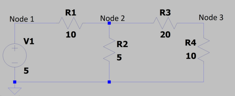
Transcribed Image Text:### Circuit Diagram Overview
This image is a circuit diagram created using LTspice, a software tool used for simulating electronic circuits. The diagram features a simple resistive circuit with one voltage source and four resistors, laid out across four nodes.
#### Components and Configuration:
1. **Voltage Source (V1):**
- Positioned between Node 0 (Ground) and Node 1.
- Voltage: 5V.
2. **Resistors:**
- **R1:** Located between Node 1 and Node 2 with a resistance of 10Ω.
- **R2:** Connected in parallel with R1 between Node 2 and Ground with a resistance of 5Ω.
- **R3:** Connected between Node 2 and Node 3 with a resistance of 20Ω.
- **R4:** Connected between Node 3 and Ground with a resistance of 10Ω.
#### Nodes:
- **Node 0:** Ground reference point.
- **Node 1:** Connected to the positive terminal of V1 and one end of R1.
- **Node 2:** Junction point connected to the other end of R1, one end of R2, and the beginning of R3.
- **Node 3:** Junction point connected to the other end of R3, beginning of R4.
### Analysis:
This circuit can be analyzed to determine the current flow through each resistor, the voltage drop across each component, and the overall circuit behavior, using techniques such as Kirchhoff's laws and Ohm's law. The parallel configuration of R2 impacts the total resistance faced by the voltage source V1, influencing current distribution within the circuit.
### Educational Usage:
Understanding this circuit setup is fundamental in electronics for illustrating how basic components interact. It serves as a useful example of applying theoretical principles to practical scenarios, allowing students to transition from schematic comprehension to real-world circuit design and analysis.
Expert Solution
Step 1
Given circuit,

Step by step
Solved in 3 steps with 1 images

Recommended textbooks for you
Introductory Circuit Analysis (13th Edition)
Electrical Engineering
ISBN:
9780133923605
Author:
Robert L. Boylestad
Publisher:
PEARSON

Delmar's Standard Textbook Of Electricity
Electrical Engineering
ISBN:
9781337900348
Author:
Stephen L. Herman
Publisher:
Cengage Learning

Programmable Logic Controllers
Electrical Engineering
ISBN:
9780073373843
Author:
Frank D. Petruzella
Publisher:
McGraw-Hill Education
Introductory Circuit Analysis (13th Edition)
Electrical Engineering
ISBN:
9780133923605
Author:
Robert L. Boylestad
Publisher:
PEARSON
Delmar's Standard Textbook Of Electricity
Electrical Engineering
ISBN:
9781337900348
Author:
Stephen L. Herman
Publisher:
Cengage Learning
Programmable Logic Controllers
Electrical Engineering
ISBN:
9780073373843
Author:
Frank D. Petruzella
Publisher:
McGraw-Hill Education

Fundamentals of Electric Circuits
Electrical Engineering
ISBN:
9780078028229
Author:
Charles K Alexander, Matthew Sadiku
Publisher:
McGraw-Hill Education

Electric Circuits. (11th Edition)
Electrical Engineering
ISBN:
9780134746968
Author:
James W. Nilsson, Susan Riedel
Publisher:
PEARSON

Engineering Electromagnetics
Electrical Engineering
ISBN:
9780078028151
Author:
Hayt, William H. (william Hart), Jr, BUCK, John A.
Publisher:
Mcgraw-hill Education,