Using the figure be below, a) Calculate P3 (in W). and b) Find the total power (in W) supplied by the source.
Using the figure be below, a) Calculate P3 (in W). and b) Find the total power (in W) supplied by the source.

Introductory Circuit Analysis (13th Edition)
13th Edition
ISBN:9780133923605
Author:Robert L. Boylestad
Publisher:Robert L. Boylestad
Chapter1: Introduction
Section: Chapter Questions
Problem 1P: Visit your local library (at school or home) and describe the extent to which it provides literature...

Related questions

Question
Using the figure be below, a) Calculate P3 (in W). and b) Find the total power (in W) supplied by the source.

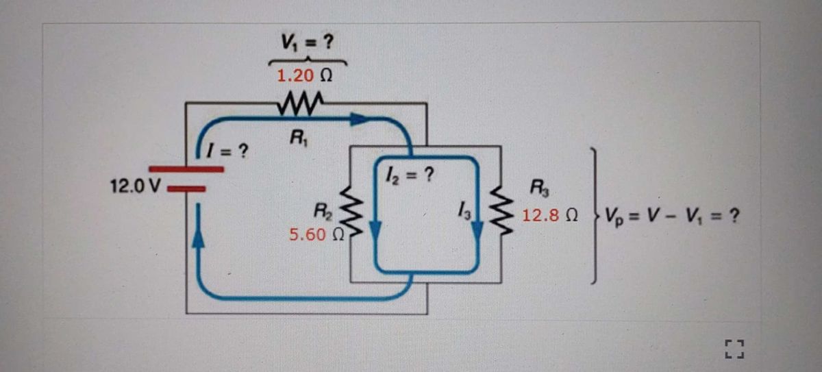
Transcribed Image Text:The image depicts an electrical circuit diagram designed to analyze a series-parallel combination of resistors and the corresponding electric currents flowing through them. Here's a detailed transcription and explanation:
**Electrical Circuit Components:**
1. **Voltage Source**:
- A battery with a voltage of 12.0 V is connected to the circuit.
2. **Resistors in the Circuit**:
- **R1**: 1.20 Ω
- **R2**: 5.60 Ω
- **R3**: 12.8 Ω
3. **Current Loops and Notations**:
- The current flowing through R1 is denoted as \( I_1 \).
- The current flowing through R2 is denoted as \( I_2 \).
- The current flowing through R3 is denoted as \( I_3 \).
4. **Voltage Drops and Equations**:
- \( V_1 \): Voltage drop across R1. It is to be calculated.
- \( V_p = V - V_1 \): This represents the voltage in the portion of the circuit exclusive of \( V_1 \). This voltage needs to be determined as well.
**Circuit Configuration**:
- The circuit starts with the 12.0 V voltage source, and the current is directed from the positive terminal into the loop.
- Resistors R1, R2, and R3 are arranged such that R2 and R3 form a parallel combination, which then combines in series with R1.
- The current entering the circuit (\( I_1 \)) passes through R1 first, causing a voltage drop labeled \( V_1 \).
- After R1, the current splits into two branches: one through R2 and another through R3.
- The combination of R2 and R3 as parallel resistors influences the overall current flow and resultant voltage drops in each branch.
**Purpose of the Diagram**:
This circuit diagram is typically used to apply Kirchhoff's voltage and current laws to determine unknown values, such as \( I_1, I_2, I_3, V_1, \) and \( V_p \). Students or users may calculate these values using the known resistances and supplied voltage, enhancing understanding of series and parallel circuits.
Expert Solution
Step 1: Determination of given parameters,
The circuit diagram,

Step by step
Solved in 4 steps with 9 images

Knowledge Booster


Learn more about
Need a deep-dive on the concept behind this application? Look no further. Learn more about this topic, electrical-engineering and related others by exploring similar questions and additional content below.Recommended textbooks for you
Introductory Circuit Analysis (13th Edition)
Electrical Engineering
ISBN:
9780133923605
Author:
Robert L. Boylestad
Publisher:
PEARSON

Delmar's Standard Textbook Of Electricity
Electrical Engineering
ISBN:
9781337900348
Author:
Stephen L. Herman
Publisher:
Cengage Learning

Programmable Logic Controllers
Electrical Engineering
ISBN:
9780073373843
Author:
Frank D. Petruzella
Publisher:
McGraw-Hill Education
Introductory Circuit Analysis (13th Edition)
Electrical Engineering
ISBN:
9780133923605
Author:
Robert L. Boylestad
Publisher:
PEARSON
Delmar's Standard Textbook Of Electricity
Electrical Engineering
ISBN:
9781337900348
Author:
Stephen L. Herman
Publisher:
Cengage Learning
Programmable Logic Controllers
Electrical Engineering
ISBN:
9780073373843
Author:
Frank D. Petruzella
Publisher:
McGraw-Hill Education

Fundamentals of Electric Circuits
Electrical Engineering
ISBN:
9780078028229
Author:
Charles K Alexander, Matthew Sadiku
Publisher:
McGraw-Hill Education

Electric Circuits. (11th Edition)
Electrical Engineering
ISBN:
9780134746968
Author:
James W. Nilsson, Susan Riedel
Publisher:
PEARSON

Engineering Electromagnetics
Electrical Engineering
ISBN:
9780078028151
Author:
Hayt, William H. (william Hart), Jr, BUCK, John A.
Publisher:
Mcgraw-hill Education,