3. Clipper and Clamper Circuits 3.1 A diode clipper Diodes may be used in a number of ways to change the shape or form of a signal. For example, the diode clipper of Fig. 3 may be used to limit the amplitude of an ac signal. Y 10k Fg 3a (b) od pa (a) Set up the circuit of Fig. 3a. Use the signal generator at 1 kHz to provide an input sinusoidal signal at 8 Vpp. Display both vi and vo on the oscilloscope (use de coupling). The output vo should be as shown in Fig 3. Sketch your input and output waveforms TUS 2024C CHI 2N CRAN Auto FOUR CHANNEL M Pos: 0.000 ААААА 30 4-Aug-22 1047 CH/ < www. naw MEASURE CHI Pied 1.000m? CHI Freg 1.007 CHI SIMS 2.06V CHO PMS 2.700 CH₂ Fg 3b 200 MH 205/ Using the constant drop model for the diode explains this result. = The output Vo Yellow Vi = Blue

Introductory Circuit Analysis (13th Edition)
13th Edition
ISBN:9780133923605
Author:Robert L. Boylestad
Publisher:Robert L. Boylestad
Chapter1: Introduction
Section: Chapter Questions
Problem 1P: Visit your local library (at school or home) and describe the extent to which it provides literature...
icon
Related questions
Question

Please answer question (b)

3. Clipper and Clamper Circuits
3.1 A diode clipper
Diodes may be used in a number of ways to change the shape or form of a signal. For
example, the diode clipper of Fig. 3 may be used to limit the amplitude of an ac signal.
Y
10kD
(b)
Fg 3a
od pu
Set up the circuit of Fig. 3a. Use the signal generator at 1 kHz to provide an input
sinusoidal signal at 8 Vpp. Display both vi and vo on the oscilloscope (use de coupling).
The output vo should be as shown in Fig 3.
Sketch your input and output waveforms
TUS 2024C FOUR CHWING
CHỈ LINH
Auto
DO STORAGE OSCE LOGO
MPos: 0.000s
ААААА
4500
4-Aug-22 1047
<
CHIN
Le
na now
MEASURE
CHI
Period
1.0007
CHI
Freq
1.00?
CH1
RMS
2.06V
CH₂
AMS
2701
CH₂
Fre
Fg 3b
200 MHz
205/
Sove
Using the constant drop model for the diode explains this result.
The output Vo = Yellow
Vi = Blue
Transcribed Image Text:3. Clipper and Clamper Circuits 3.1 A diode clipper Diodes may be used in a number of ways to change the shape or form of a signal. For example, the diode clipper of Fig. 3 may be used to limit the amplitude of an ac signal. Y 10kD (b) Fg 3a od pu Set up the circuit of Fig. 3a. Use the signal generator at 1 kHz to provide an input sinusoidal signal at 8 Vpp. Display both vi and vo on the oscilloscope (use de coupling). The output vo should be as shown in Fig 3. Sketch your input and output waveforms TUS 2024C FOUR CHWING CHỈ LINH Auto DO STORAGE OSCE LOGO MPos: 0.000s ААААА 4500 4-Aug-22 1047 < CHIN Le na now MEASURE CHI Period 1.0007 CHI Freq 1.00? CH1 RMS 2.06V CH₂ AMS 2701 CH₂ Fre Fg 3b 200 MHz 205/ Sove Using the constant drop model for the diode explains this result. The output Vo = Yellow Vi = Blue
Expert Solution
steps

Step by step

Solved in 3 steps with 2 images

Blurred answer
Follow-up Questions
Read through expert solutions to related follow-up questions below.
Follow-up Question

continue from the previous question.

O
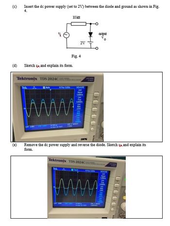
(d)
Insert the dc power supply (set to 2V) between the diode and ground as shown in Fig.
4.
(e)
Tektronix TDS 2024C)
10 kg
Sketch and explain its form.
Fig. 4
2V
www.
MEASURE
1000
C
F
Tektronix TDS 2024C
FO
Remove the dc power supply and reverse the diode. Sketch and explain its
form.
+--
000000
Mo
лиш
autput
MEASURE
0000
Transcribed Image Text:O (d) Insert the dc power supply (set to 2V) between the diode and ground as shown in Fig. 4. (e) Tektronix TDS 2024C) 10 kg Sketch and explain its form. Fig. 4 2V www. MEASURE 1000 C F Tektronix TDS 2024C FO Remove the dc power supply and reverse the diode. Sketch and explain its form. +-- 000000 Mo лиш autput MEASURE 0000
Solution
Bartleby Expert
SEE SOLUTION
Knowledge Booster
Three Phase Transformer
Learn more about
Need a deep-dive on the concept behind this application? Look no further. Learn more about this topic, electrical-engineering and related others by exploring similar questions and additional content below.
Recommended textbooks for you
Introductory Circuit Analysis (13th Edition)
Electrical Engineering
ISBN:
9780133923605
Author:
Robert L. Boylestad
Publisher:
PEARSON
Delmar's Standard Textbook Of Electricity
Electrical Engineering
ISBN:
9781337900348
Author:
Stephen L. Herman
Publisher:
Cengage Learning
Programmable Logic Controllers
Electrical Engineering
ISBN:
9780073373843
Author:
Frank D. Petruzella
Publisher:
McGraw-Hill Education
Fundamentals of Electric Circuits
Electrical Engineering
ISBN:
9780078028229
Author:
Charles K Alexander, Matthew Sadiku
Publisher:
McGraw-Hill Education
Electric Circuits. (11th Edition)
Electrical Engineering
ISBN:
9780134746968
Author:
James W. Nilsson, Susan Riedel
Publisher:
PEARSON
Engineering Electromagnetics
Electrical Engineering
ISBN:
9780078028151
Author:
Hayt, William H. (william Hart), Jr, BUCK, John A.
Publisher:
Mcgraw-hill Education,