The voltages v1, V2, V3, and v4 are the node voltages corresponding to nodes 1, 2, 3, and 4 in the below Figure. The value of node voltage vị is 25 V. Determine the values of v2, V3, and v4 node voltages. 10 2 3ip 20 2 b 25 V Va 30 2 2 A
![The voltages v1, V2, V3, and v4 are the node voltages corresponding to nodes 1, 2, 3,
and 4 in the below Figure. The value of node voltage v, is 25 V. Determine the values
of v2, V3, and v4 node voltages.
5va
10 2
+
3ip
20 Q b
25 V
Va 30 2
2 A
1:26 F
49°F Mostly cloudy
2/20/2
P Type here to search
Home
F9
End
F10
PgUp.
PgDn
DII
PrtScn
F8
F12
Esc
F4
F7
F1
F2
F3
&](/v2/_next/image?url=https%3A%2F%2Fcontent.bartleby.com%2Fqna-images%2Fquestion%2F6e11f595-a40a-4bf3-b7d2-0a0cab1f1556%2Ff889689c-f769-4605-964e-1815dcbf40d5%2F6gim7dr_processed.jpeg&w=3840&q=75)
![](/static/compass_v2/shared-icons/check-mark.png)
In general, in a N node circuit, one of the nodes is chosen as reference or datum node, then it is possible to write N-1 model equations by assuming N-1 node voltages. We assume zero potential for the reference node. Let us take an example to illustrate the method.
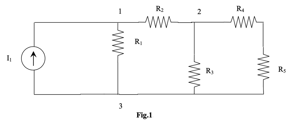
In the circuit shown in Fig. 1, node 3 is assumed as the reference node. The voltage at node 1 is the voltage at that node with respect to node 3. Similarly, the voltage at node 2 is the voltage at that node with respect to node 3.
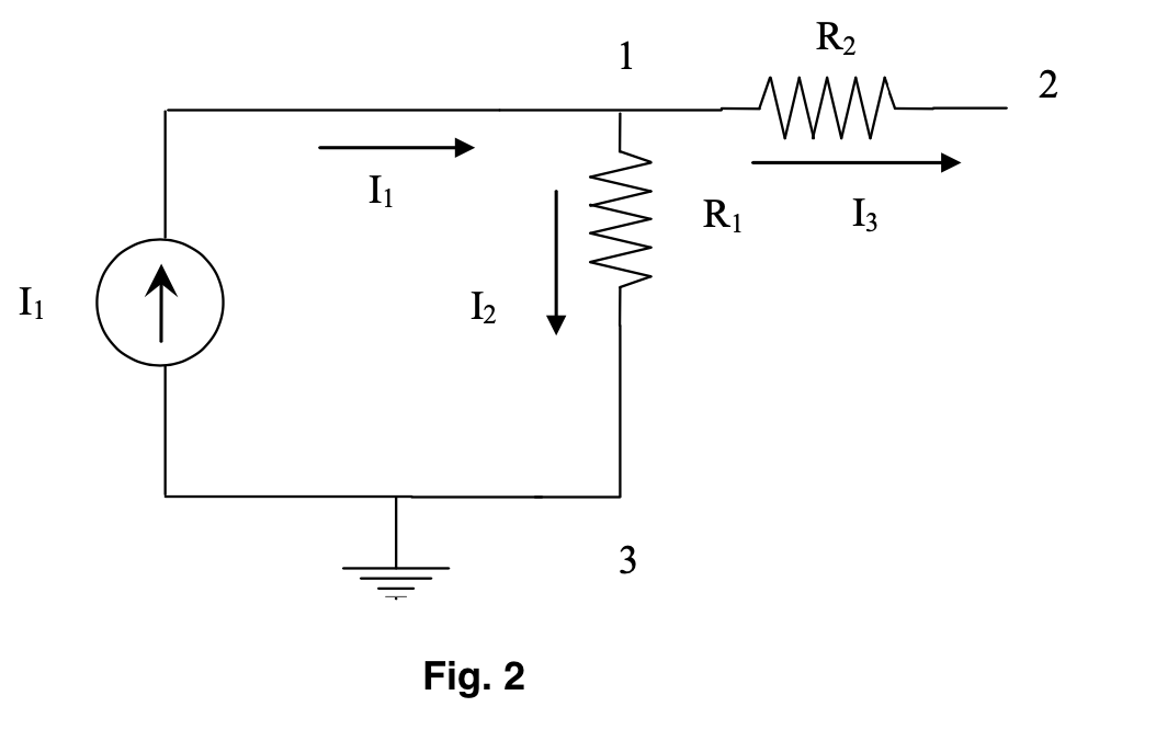
Applying KCL at node 1 ; the current entering is equal to the current leaving (refer Fig. 2)
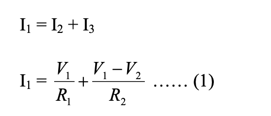
Where V1 and V2 are the voltages at node 1 and 2, respectively. Similarly, at node2, the current entering is
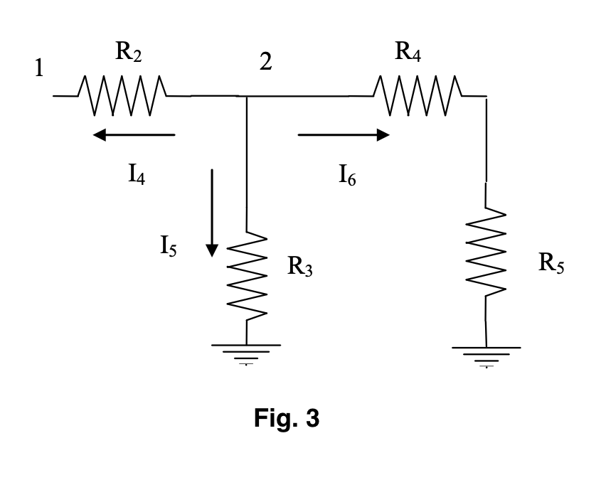
equal to the current leaving as shown in Fig. 3.
Trending now
This is a popular solution!
Step by step
Solved in 2 steps with 7 images
![Blurred answer](/static/compass_v2/solution-images/blurred-answer.jpg)
![Introductory Circuit Analysis (13th Edition)](https://www.bartleby.com/isbn_cover_images/9780133923605/9780133923605_smallCoverImage.gif)
![Delmar's Standard Textbook Of Electricity](https://www.bartleby.com/isbn_cover_images/9781337900348/9781337900348_smallCoverImage.jpg)
![Programmable Logic Controllers](https://www.bartleby.com/isbn_cover_images/9780073373843/9780073373843_smallCoverImage.gif)
![Fundamentals of Electric Circuits](https://www.bartleby.com/isbn_cover_images/9780078028229/9780078028229_smallCoverImage.gif)
![Electric Circuits. (11th Edition)](https://www.bartleby.com/isbn_cover_images/9780134746968/9780134746968_smallCoverImage.gif)
![Engineering Electromagnetics](https://www.bartleby.com/isbn_cover_images/9780078028151/9780078028151_smallCoverImage.gif)