The top part of the table shows the computation for the corner columns at grid point A-1. Fill out the lower part of Table 1 and provide the column load calculation for the interior column at grid point B-2 Column Dead Load Column Live Load Level 5th 4th Corner Column A-1 (example) Roof 414 ft² 150 psf 3rd 2nd 5th 4th Tributary area, AT per level (ft²) 3rd (a) 2nd 414 ft² Interior Column B-2 Roof 414 ft² 414 ft² 414 ft² Per unit area (psf) (b) ● 180 psf 180 psf 180 psf 210 psf 150 psf 180 psf 180 psf 180 psf 210 psf Load per Floor (kips) (c)=(a)*(b) 62 k 75 k 75 k 75 k 87 k Sum DL levels above (kips) (d) = {(c) 62 k 137 k 211 k 286 k 373 k Reduced Live Load (psf) (e) 20 psf 30 psf 25 psf 20 psf 100 psf 20 psf 50 psf 50 psf 50 psf 100 psf Load per Floor (kips) (f)=(a)*(e) 8 k 12 k 10 k 8 k 41 k Sum LL levels above ≤0.4 (kips) (g) =Σ(e) 8 k 12 k 22 k 30 k 71 k The tributary area of the column at each floor is: AT = (13 ft +7.33 ft)² = 414 ft² Column loads at each level are calculated by multiplying the tributary area by unit load The load from upper level columns are added to obtain the load at the lower columns Roof live load is not required to be added to floor live loads Live load reduction factor applies to the columns where their accumulated tributary area (AT) is larger than 100 ft². The reduction factor varies is calculated using the code equation and it varies at each floor. 15 Live Load Reduction Factor = 0.25 + √4. AT (AT is the sum of tributary area of floors above in ft²) Live loads larger than 100 psf cannot be reduced. The column's factored design load is: U = 1.2 D+1.6 L Factored Load U=1.2D +1.6L (kip) 1.2(d)+1.6(g) 88 k 184 k 288 k 391k 561k
The top part of the table shows the computation for the corner columns at grid point A-1. Fill out the lower part of Table 1 and provide the column load calculation for the interior column at grid point B-2 Column Dead Load Column Live Load Level 5th 4th Corner Column A-1 (example) Roof 414 ft² 150 psf 3rd 2nd 5th 4th Tributary area, AT per level (ft²) 3rd (a) 2nd 414 ft² Interior Column B-2 Roof 414 ft² 414 ft² 414 ft² Per unit area (psf) (b) ● 180 psf 180 psf 180 psf 210 psf 150 psf 180 psf 180 psf 180 psf 210 psf Load per Floor (kips) (c)=(a)*(b) 62 k 75 k 75 k 75 k 87 k Sum DL levels above (kips) (d) = {(c) 62 k 137 k 211 k 286 k 373 k Reduced Live Load (psf) (e) 20 psf 30 psf 25 psf 20 psf 100 psf 20 psf 50 psf 50 psf 50 psf 100 psf Load per Floor (kips) (f)=(a)*(e) 8 k 12 k 10 k 8 k 41 k Sum LL levels above ≤0.4 (kips) (g) =Σ(e) 8 k 12 k 22 k 30 k 71 k The tributary area of the column at each floor is: AT = (13 ft +7.33 ft)² = 414 ft² Column loads at each level are calculated by multiplying the tributary area by unit load The load from upper level columns are added to obtain the load at the lower columns Roof live load is not required to be added to floor live loads Live load reduction factor applies to the columns where their accumulated tributary area (AT) is larger than 100 ft². The reduction factor varies is calculated using the code equation and it varies at each floor. 15 Live Load Reduction Factor = 0.25 + √4. AT (AT is the sum of tributary area of floors above in ft²) Live loads larger than 100 psf cannot be reduced. The column's factored design load is: U = 1.2 D+1.6 L Factored Load U=1.2D +1.6L (kip) 1.2(d)+1.6(g) 88 k 184 k 288 k 391k 561k

Chapter2: Loads On Structures
Section: Chapter Questions
Problem 1P

Related questions

Question

Transcribed Image Text:The top part of the table shows the computation for the corner columns at grid point A-1. Fill out the lower part of
Table 1 and provide the column load calculation for the interior column at grid point B-2
Level
Column Dead Load
Column Live Load
5th
4th
Corner Column A-1 (example)
Roof
414 ft²
150 psf
3rd
2nd
5th
4th
Tributary
area, AT
per level
(ft²)
3rd
(a)
2nd
414 ft²
Interior Column B-2
Roof
414 ft²
414 ft²
414 ft²
●
Per unit
area
(psf)
(b)
●
180 psf
180 psf
180 psf
210 psf
150 psf
180 psf
180 psf
180 psf
210 psf
Load per
Floor
(kips)
(c)=(a)*(b)
62 k
75 k
75 k
75 k
87 k
Sum DL levels
above
(kips)
(d) = [(c)
62 k
137 k
211 k
286 k
373 k
Reduced
Live Load
(psf)
(e)
20 psf
30 psf
25 psf
20 psf
100 psf
20 psf
50 psf
50 psf
50 psf
100 psf
Load per Floor
(kips)
(f)=(a)*(e)
8 k
12 k
10 k
8 k
41 k
Sum LL
levels above
(kips)
(g) =[(e)
15
√√4. AT
8 k
≤ 0.4
12 k
22 k
30 k
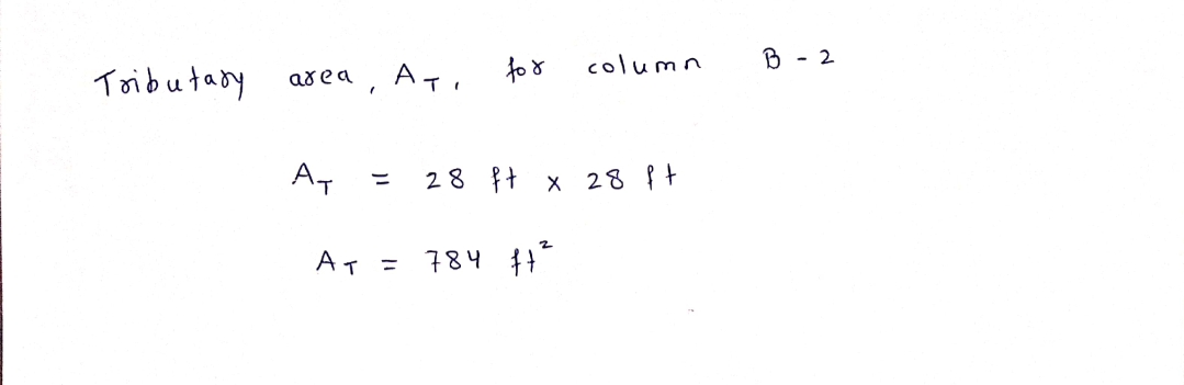
The tributary area of the column at each floor is:
AT = (13 ft +7.33 ft)² = 414 ft²
Column loads at each level are calculated by multiplying the tributary area by unit load
The load from upper level columns are added to obtain the load at the lower columns
Roof live load is not required to be added to floor live loads
71 k
Live load reduction factor applies to the columns where their accumulated tributary
area (AT) is larger than 100 ft². The reduction factor varies is calculated using the code
equation and it varies at each floor.
Live Load Reduction Factor =
0.25 +
(AT is the sum of tributary area of floors above in ft²)
Live loads larger than 100 psf cannot be reduced.
The column's factored design load is: U = 1.2 D+1.6 L
Factored Load
U=1.2D +1.6L
(kip)
1.2(d)+1.6(g)
88 k
184 k
288 k
391k
561k

Transcribed Image Text:8.14 Shown below is the floor framing plan and section of a concrete building. Table 7-3, on the next page, shows an example of
the column load computation. The top part of the table shows the computation for the corner columns at grid point A-1.
7-4"
F
26'-0"
E
30-0"
D
Rectangular
Column, Typ-
Concrete
Core Wall
156¹-8"
30-0⁰
== 年
C
30¹-0⁰
B
=_====_===
26'-0"
Perimeter Moment.
Frame Beam
(32 Widex36"Deep),
Тур
A
Building Section B
===
=====
=
Typical Floor Framing Plan A
26'-0"
30-0"
30¹-0⁰
30-0⁰
426-0²
4@13'-0"=52¹-0"
18¹-0¹
70'-0"
2
5
156¹-8"
Expert Solution
Step 1

Step by step
Solved in 2 steps with 2 images

Knowledge Booster


Learn more about
Need a deep-dive on the concept behind this application? Look no further. Learn more about this topic, civil-engineering and related others by exploring similar questions and additional content below.Recommended textbooks for you

Structural Analysis (10th Edition)
Civil Engineering
ISBN:
9780134610672
Author:
Russell C. Hibbeler
Publisher:
PEARSON

Principles of Foundation Engineering (MindTap Cou…
Civil Engineering
ISBN:
9781337705028
Author:
Braja M. Das, Nagaratnam Sivakugan
Publisher:
Cengage Learning
Structural Analysis (10th Edition)
Civil Engineering
ISBN:
9780134610672
Author:
Russell C. Hibbeler
Publisher:
PEARSON
Principles of Foundation Engineering (MindTap Cou…
Civil Engineering
ISBN:
9781337705028
Author:
Braja M. Das, Nagaratnam Sivakugan
Publisher:
Cengage Learning

Fundamentals of Structural Analysis
Civil Engineering
ISBN:
9780073398006
Author:
Kenneth M. Leet Emeritus, Chia-Ming Uang, Joel Lanning
Publisher:
McGraw-Hill Education


Traffic and Highway Engineering
Civil Engineering
ISBN:
9781305156241
Author:
Garber, Nicholas J.
Publisher:
Cengage Learning