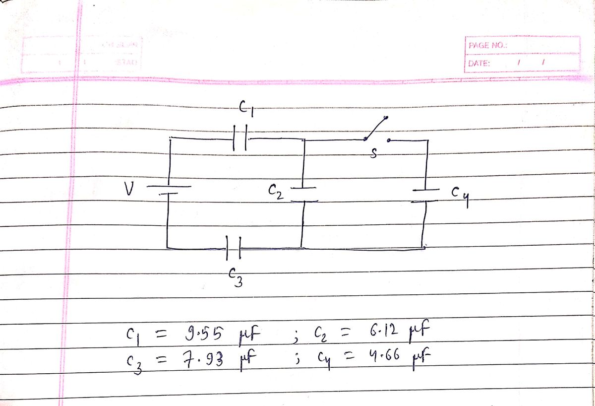
The figure shows capacitor 1 (C1 = 9.55 µF), capacitor 2 (C2 = 6.12 µF), and capacitor 3 (C3 = 7.93 µF) connected to a 13.4 V battery. When switch S is closed so as to connect uncharged capacitor 4 (C4 = 4.66 µF), (a) how much charge passes through point P from the battery and (b) how much charge shows up on capacitor 4? S V (a) Number Units (b) Number i Units >
Q: Four capacitors are connected as shown in the figure below. (C = 14.0 μF.) C 3.00 με th |20.0 με HE…
A:
Q: Two capacitors, C, = 16.0 µF and C, = 30.0 pF, are connected in series, and a 15.0-V battery is…
A:
Q: Consider the following. (LetC₁ = 25.60 μF and C₂ = 19.60 μF.) 6.00 με C₁ C₂ C₁ + 9.00 V (a) Find the…
A:
Q: Four capacitors are connected as shown in Fig C1 = 4.50 μF, C2 = 7.50 μF, C3 = 2.50 μF and C4 =…
A: in this question combination of capacitors are shown in circuit we determine which capacitor are…
Q: In the figure to the right, the battery has potential difference V = 9.0 V, C2 = 3.0 uF, and C4 =…
A: As we know the relationship between charge (Q) and voltage (V) is, Q = CV ---------(1) If…
Q: A 13.0-uF capacitor and a 50.0-μF capacitor are charged by being connected across separate 45.0-V…
A: It is given that, . The battery voltage is .
Q: Three capacitors and a battery are connected as shown. The capacitance values are C₁ = 8.1 µF, C₂ =…
A:
Q: In the figure below, capacitor 1 (C1 = 24.0 µF) initially has a potential difference of 60.0 V…
A:
Q: In (Figure 1), let C₁ = 3.20 μF, C2 = 5.50 μF, and Vab = 60.0 V. For related problem-solving tips…
A:
Q: Three capacitors, C₁ = 5.67 μµF, C₂ = 18.4 μF, and C3 = 16.1 μF, are connected and wired to a 12-V…
A:
Q: Two capacitors (C₁ = 4.00 μF and C₂ = 14.0 μF) are now connected in series and to a 9.00-V battery…
A: We are given 2 capacitors. We are given their values. We are also given the voltage of battery. We…
Q: (a) A 1.50 μF capacitor and a 4.75 μF capacitor are connected in series across a 7.50 V battery. How…
A:
Q: Consider the following. (LetC, = 40.40 µF and c, = 34.40 µF.) 6.00 µF C2 + 9.00 V (a) Find the…
A: Please see the answers below.
Q: (a) What is the equivalent capacitance (in pF) of all the capacitors in the entire circult? uF (b)…
A: here we have given the capacitance of four capacitor C1=19.20, C2=13.20 AND combination of capacitor…
Q: Two capacitors C1 = 2 µF, and C2 = 9 µF are connected in series to a 10V battery. The two capacitors…
A:
Q: Three capacitors C, = 10.1 µF, C, = 22.0 µF, and Cz = 29.3 µF are connected in parallel. To avoid…
A: Capacitors are connected in parallel, so the voltage across them is the same. We know Q = CV As…
Q: The figure shows capacitor 1 (C₁ = 8.63 uF), capacitor 2 (C₂=4.71 µF), and capacitor 3 (C3= 6.90 uF)…
A: Given:- The capacitance of the circuit is as C1= 8.63 μF C3= 6.90 μFC2= 4.71 μF C4= 7.32…
Q: 4. Find the charge and the voltage on each of the following capacitors. C, = 3.00 µF , C2 = 6.00 µF,…
A: The capacitance of the four capacitors are given as, C1=3 μF,C2=6 μF, C3=2 μF, and C4=4 μF. The…
Q: In the figure a potential difference of V = 106 V is applied across a capacitor arrangement with…
A:
Q: Consider the circuit shown in the figure, with C₁ = 6.72 μF and C₂ = 8.24 μF. 6.00 µF 47 2.00 uF C₂…
A: Since you have posted a question with multiple sub-parts, we will solve the first three subparts for…
Q: In the figure the battery has potential difference V = 9.50 V, C₂ = 3.20 µF, C4 = 4.90 μF, and all…
A:
Q: Figure shows a 12.0 V battery and four uncharged capacitors of capacitances C = 1.00 µF, C2 = C4 =…
A: Voltage of battery V = 12V C1 = 1 μF C2 = 2 μF C3 = 3 μF C4 = 4 μF Only switch S1 is closed, charge…
Q: Problem 4: Three capacitors are connected as shown in the figure. C1 = 7.8 µF, C2 = 9.2 µF, C3 = 2.6…
A:
Q: Problem 2: Three capacitors are connected as shown in the figure. C, = 6.8 µF, C, = 8.2 µF, C3 = 6.7…
A:
Q: 24Je are in the of capacitors are C-1.SuF, C 3.SF, C 2.OuF, Ce 2SuF, C 3.0aF and C-4.0µF. The…
A: C1=1.5uF, C2= 3.5uF, C3= 2.0uF, C4=2.5uF, C5= 3.0uF C6=4.0uF voltage V = 12.0V
Q: (a) A 3.00 μF capacitor and a 4.50 μF capacitor are connected in series across a 7.00 V battery. How…
A:
Q: = 12.0 V battery, and the C2 = 9.41 capacitor is uncharged. With the switch in position A, the C1 =…
A:
Q: Two capacitors, C1 = 25.0 µF and C2 = 32.0 µF, are connected in series, and a 15.0-V battery is…
A:
Q: A capacitor C1=1.0μF is charged up to a voltage V=60V by connecting it to a battery B through…
A: Answer : When switch (2) is closed, the capacitors C1, C2, and C3 are connected in parallel. The…
Q: The figure shows capacitor 1 (C₁-8.19 μF), capacitor 2 (C₂-4.71 µF), and capacitor 3 (C3-9.56 µF)…
A:
Q: : Four capacitors are arranged in the following configuration: the capacitances of capacitors are…
A:
Trending now
This is a popular solution!
Step by step
Solved in 2 steps with 2 images
- In the figure a potential difference of V = 91.2 V is applied across a capacitor arrangement with capacitances C₁ = 11.0 µF, C₂ = 5.62 µF, and C3 = 4.58 µF. If capacitor 3 undergoes electrical breakdown so that it becomes equivalent to conducting wire, what is the increase in (a) the charge on capacitor 1 and (b) the potential difference across capacitor 1? (a) Number i (b) Number i ! ! Units Units C₂ с V C₂In the figure a 27 V battery is connected across capacitors of capacitances C₁ = C6 = 4.5 µF and C3 = C₁ = 2.5C₂ = 2.5C4 = 6.0 μF. What are (d) q1 of capacitor 1, (e) V₂ and (f) q2 of capacitor 2, and (g) v3 and (h) 93 of capacitor 3? C4 C3 # C₁ C₁If a voltage source of 24.0 V is connected from top to bottom, what is the charge accumulated on the 3.5 µF capacitor, in µC, when fully charged?
- Please answer vii, viiiTwo capacitors, C1 = 5.92 µF and C2 = 3.30 µF, are connected in parallel, then the combination is connected to a 250 V battery. When the capacitors are charged, each one is removed from the circuit. Next, the two charged capacitors are connected to each other so that the positive plate of one capacitor is connected to the negative plate of the other capacitor. What is the resulting charge on each capacitor (in µC)? q′1= µC q′2= µC (b) What If? What is the resulting charge on each capacitor (in µC) if they are instead charged as a series combination and then connected positive plate to positive plate and negative plate to negative plate? q′1= µC q′2= µCThe capacitors in the figure are initially uncharged. The capacitances are C₁ = 3.3 µF, C₂-9.6 μF, and C3= 10 μF, and the battery's potential difference is V 11 V. When switch S is closed, how many electrons travel through (a) point a, (b) point b. (c) point c, and (d) point d? (e) In the figure, do the electrons travel up or down through point b? (f) In the figure, do the electrons travel up or down through point c? I!! (a) Number (b) Number (c) Number (d) Number (e) b Units Units Units Units
- (a) A 2.25 µF capacitor and a 5.00 µF capacitor are connected in series across a 2.00 V battery. How much charge (in µC) is stored on each capacitor? 2.25 MF cаpacitor 5.00 µF capacitor (b) The same two capacitors are disconnected and discharged. They are then connected in parallel across the same battery. How much charge (in µC) is stored on each capacitor now? 2.25 µF capacitor X µC 5.00 µF capacitor X µcTwo capacitors C1 = 2 µF, and C2 = 6 µF are connected in series to a 10V battery. The two capacitors are fully charged. What is the energy (expressed in "HJ") stored in capacitor C1? C, V Answer: Answer