0 ft (assume this is 1000.00 ft). The flowrate in the system from ervoir is 5 cfs. Assume the water temperature is 50 °F. The pipe s 300 ft, the pipe length from the globe valve to the enlargemen rcy Weisbach equation for pipe friction head loss, find the elev nt for minor losses. Also tabulate the total head at each of the f after the sharp-edged pipe entrance, B before the globe valve, C
0 ft (assume this is 1000.00 ft). The flowrate in the system from ervoir is 5 cfs. Assume the water temperature is 50 °F. The pipe s 300 ft, the pipe length from the globe valve to the enlargemen rcy Weisbach equation for pipe friction head loss, find the elev nt for minor losses. Also tabulate the total head at each of the f after the sharp-edged pipe entrance, B before the globe valve, C
Chapter2: Loads On Structures
Section: Chapter Questions
Problem 1P
Related questions
Question

Transcribed Image Text:Problem 2
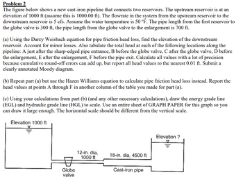
The figure below shows a new cast-iron pipeline that connects two reservoirs. The upstream reservoir is at an
elevation of 1000 ft (assume this is 1000.00 ft). The flowrate in the system from the upstream reservoir to the
downstream reservoir is 5 cfs. Assume the water temperature is 50 °F. The pipe length from the first reservoir to
the globe valve is 300 ft, the pipe length from the globe valve to the enlargement is 700 ft.
(a) Using the Darcy Weisbach equation for pipe friction head loss, find the elevation of the downstream
reservoir. Account for minor losses. Also tabulate the total head at each of the following locations along the
pipeline: A just after the sharp-edged pipe entrance, B before the globe valve, C after the globe valve, D before
the enlargement, E after the enlargement, F before the pipe exit. Calculate all values with a lot of precision
because cumulative round-off errors can add up, but report all head values to the nearest 0.01 ft. Submit a
clearly annotated Moody diagram.
(b) Repeat part (a) but use the Hazen Williams equation to calculate pipe friction head loss instead. Report the
head values at points A through F in another column of the table you made for part (a).
(c) Using your calculations from part (b) (and any other necessary calculations), draw the energy grade line
(EGL) and hydraulic grade line (HGL) to scale. Use an entire sheet of GRAPH PAPER for this graph so you
can draw it large enough. The horizontal scale should be different from the vertical scale.
Elevation 1000 ft
Globe
valve
12-in. dia,
1000 ft
18-in. dia, 4500 ft
Cast-iron pipe
Elevation ?
Expert Solution
This question has been solved!
Explore an expertly crafted, step-by-step solution for a thorough understanding of key concepts.
This is a popular solution!
Trending now
This is a popular solution!
Step by step
Solved in 3 steps with 1 images

Follow-up Questions
Read through expert solutions to related follow-up questions below.
Follow-up Question
can I please get help with part a

Transcribed Image Text:Problem 2
The figure below shows a new cast-iron pipeline that connects two reservoirs. The upstream reservoir is at an
elevation of 1000 ft (assume this is 1000.00 ft). The flowrate in the system from the upstream reservoir to the
downstream reservoir is 5 cfs. Assume the water temperature is 50 °F. The pipe length from the first reservoir to
the globe valve is 300 ft, the pipe length from the globe valve to the enlargement is 700 ft.
(a) Using the Darcy Weisbach equation for pipe friction head loss, find the elevation of the downstream
reservoir. Account for minor losses. Also tabulate the total head at each of the following locations along the
pipeline: A just after the sharp-edged pipe entrance, B before the globe valve, C after the globe valve, D before
the enlargement, E after the enlargement, F before the pipe exit. Calculate all values with a lot of precision
because cumulative round-off errors can add up, but report all head values to the nearest 0.01 ft. Submit a
clearly annotated Moody diagram.
(b) Repeat part (a) but use the Hazen Williams equation to calculate pipe friction head loss instead. Report the
head values at points A through F in another column of the table you made for part (a).
(c) Using your calculations from part (b) (and any other necessary calculations), draw the energy grade line
(EGL) and hydraulic grade line (HGL) to scale. Use an entire sheet of GRAPH PAPER for this graph so you
can draw it large enough. The horizontal scale should be different from the vertical scale.
Elevation 1000 ft
Globe
valve
12-in. dia,
1000 ft
18-in. dia, 4500 ft
Cast-iron pipe
Elevation ?
Solution
Knowledge Booster
Learn more about
Need a deep-dive on the concept behind this application? Look no further. Learn more about this topic, civil-engineering and related others by exploring similar questions and additional content below.Recommended textbooks for you


Structural Analysis (10th Edition)
Civil Engineering
ISBN:
9780134610672
Author:
Russell C. Hibbeler
Publisher:
PEARSON

Principles of Foundation Engineering (MindTap Cou…
Civil Engineering
ISBN:
9781337705028
Author:
Braja M. Das, Nagaratnam Sivakugan
Publisher:
Cengage Learning


Structural Analysis (10th Edition)
Civil Engineering
ISBN:
9780134610672
Author:
Russell C. Hibbeler
Publisher:
PEARSON

Principles of Foundation Engineering (MindTap Cou…
Civil Engineering
ISBN:
9781337705028
Author:
Braja M. Das, Nagaratnam Sivakugan
Publisher:
Cengage Learning

Fundamentals of Structural Analysis
Civil Engineering
ISBN:
9780073398006
Author:
Kenneth M. Leet Emeritus, Chia-Ming Uang, Joel Lanning
Publisher:
McGraw-Hill Education


Traffic and Highway Engineering
Civil Engineering
ISBN:
9781305156241
Author:
Garber, Nicholas J.
Publisher:
Cengage Learning