The bar shown below has a constant width of 41 mm and a thickness of 13 mm. The maximum average normal stress in the bar when it is sujected to the loading shown will be: ___ MPa. Calculate your answer to 1 decimal place.
The bar shown below has a constant width of 41 mm and a thickness of 13 mm. The maximum average normal stress in the bar when it is sujected to the loading shown will be: ___ MPa. Calculate your answer to 1 decimal place.

Elements Of Electromagnetics
7th Edition
ISBN:9780190698614
Author:Sadiku, Matthew N. O.
Publisher:Sadiku, Matthew N. O.
ChapterMA: Math Assessment
Section: Chapter Questions
Problem 1.1MA

Related questions

Question
The bar shown below has a constant width of 41 mm and a thickness of 13 mm. The maximum average normal stress in the bar when it is sujected to the loading shown will be: ___ MPa.
Calculate your answer to 1 decimal place.

Transcribed Image Text:**Problem Statement:**
The bar shown below has a constant width of 41 mm and a thickness of 13 mm. The maximum average normal stress in the bar when it is subjected to the loading shown will be: ___ MPa.
Calculate your answer to 1 decimal place.
**Diagram Explanation:**
The diagram illustrates a horizontal bar segment with four labeled sections (A, B, C, D) connected by ropes and subjected to various forces:
- Section A is pulled to the left with a force of 12 kN.
- Section B is subject to a force of 9 kN pulling to the right and a force of 9 kN pulling to the left.
- Section C is acted upon by a force of 4 kN pulling to the right and a force of 4 kN pulling to the left.
- Section D is pulled to the right with a force of 22 kN.
- The length of each segment is specified as 35 mm.
The diagram is simplified and assumes linear stress distribution and uniform cross-sectional dimensions.
Expert Solution
Step 1
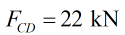
The maximum force in the section CD considering the right portion is
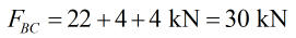
The maximum force in the section BC considering the right portion is
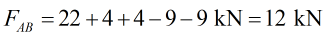
The maximum force in the section AB considering the right portion is

Step by step
Solved in 2 steps with 4 images

Knowledge Booster


Learn more about
Need a deep-dive on the concept behind this application? Look no further. Learn more about this topic, mechanical-engineering and related others by exploring similar questions and additional content below.Recommended textbooks for you
Elements Of Electromagnetics
Mechanical Engineering
ISBN:
9780190698614
Author:
Sadiku, Matthew N. O.
Publisher:
Oxford University Press

Mechanics of Materials (10th Edition)
Mechanical Engineering
ISBN:
9780134319650
Author:
Russell C. Hibbeler
Publisher:
PEARSON

Thermodynamics: An Engineering Approach
Mechanical Engineering
ISBN:
9781259822674
Author:
Yunus A. Cengel Dr., Michael A. Boles
Publisher:
McGraw-Hill Education
Elements Of Electromagnetics
Mechanical Engineering
ISBN:
9780190698614
Author:
Sadiku, Matthew N. O.
Publisher:
Oxford University Press
Mechanics of Materials (10th Edition)
Mechanical Engineering
ISBN:
9780134319650
Author:
Russell C. Hibbeler
Publisher:
PEARSON
Thermodynamics: An Engineering Approach
Mechanical Engineering
ISBN:
9781259822674
Author:
Yunus A. Cengel Dr., Michael A. Boles
Publisher:
McGraw-Hill Education

Control Systems Engineering
Mechanical Engineering
ISBN:
9781118170519
Author:
Norman S. Nise
Publisher:
WILEY

Mechanics of Materials (MindTap Course List)
Mechanical Engineering
ISBN:
9781337093347
Author:
Barry J. Goodno, James M. Gere
Publisher:
Cengage Learning

Engineering Mechanics: Statics
Mechanical Engineering
ISBN:
9781118807330
Author:
James L. Meriam, L. G. Kraige, J. N. Bolton
Publisher:
WILEY