HW4: Problem 1. Using S8MCQ rectifier diodes (a real diode), design a bridge rectifier circuit to convert 120 V rms (60 Hz) to a DC voltage of Vp-10 V (maximum voltage) and ripple voltage of Vr=0.25 V when it delivers 0.25 A to a load. By designing, it means that you have to calculate the value for the capacitor and find what should be the ratio of the primary to secondary winding of the transformer. transformer ac line 120 V (rms) 60 Hz v vi Diode rectifier m m₂ Filter Load
HW4: Problem 1. Using S8MCQ rectifier diodes (a real diode), design a bridge rectifier circuit to convert 120 V rms (60 Hz) to a DC voltage of Vp-10 V (maximum voltage) and ripple voltage of Vr=0.25 V when it delivers 0.25 A to a load. By designing, it means that you have to calculate the value for the capacitor and find what should be the ratio of the primary to secondary winding of the transformer. transformer ac line 120 V (rms) 60 Hz v vi Diode rectifier m m₂ Filter Load
Introductory Circuit Analysis (13th Edition)
13th Edition
ISBN:9780133923605
Author:Robert L. Boylestad
Publisher:Robert L. Boylestad
Chapter1: Introduction
Section: Chapter Questions
Problem 1P: Visit your local library (at school or home) and describe the extent to which it provides literature...
Related questions
Question

Transcribed Image Text:HW4: Problem 1. Using S8MCQ rectifier diodes (a real diode), design a bridge rectifier circuit to convert
120 V rms (60 Hz) to a DC voltage of Vp-10 V (maximum voltage) and ripple voltage of Vr=0.25 V when it
delivers 0.25 A to a load.
By designing, it means that you have to calculate the value for the capacitor and find what should be the
ratio of the primary to secondary winding of the transformer.
transformer
ac line
120 V (rms).
60 Hz
US
Vi
vi vi
Diode
rectifier
my
Filter
Vo
Load
Expert Solution
This question has been solved!
Explore an expertly crafted, step-by-step solution for a thorough understanding of key concepts.
This is a popular solution!
Trending now
This is a popular solution!
Step by step
Solved in 5 steps with 1 images

Follow-up Questions
Read through expert solutions to related follow-up questions below.
Follow-up Question
Thank you for your help so far.
The original question from my homework is the 1st attached image, but I just want to know 2 things.
1) How to calculate iD av and iD max?
And if you're feeling extra nice;
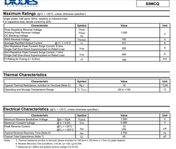
2) What are iD av and iD max called on a datasheet? I'm looking at the data sheet and I dont see any currents related to "D". I attached a 2nd picture of the datasheet I'm looking at.
If the 2nd question is too much for 1 solution on this site, please just answer my 1st question and I'll follow up with my 2nd. I don't want to type this whole question again, lol.
Thanks again!

Transcribed Image Text:DIODES.
RPORATED
Maximum Ratings (@TA = +25°C, unless otherwise specified.)
Single phase, half wave, 60Hz, resistive or inductive load.
For capacitive load, derate current by 20%.
Characteristic
Peak Repetitive Reverse Voltage
Working Peak Reverse Voltage
DC Blocking Voltage
RMS Reverse Voltage
Average Rectified Output Current
Non-Repetitive Peak Forward Surge Current, 8.3ms
Single Half Sine-Wave Superimposed on Rated Load
Non-Repetitive Peak Forward Surge Current, 1.0ms
Single Half Sine-Wave Superimposed on Rated Load
1²t Rating for Fusing (t < 8.3ms)
Thermal Characteristics
Characteristic
Typical Thermal Resistance, Junction to Terminal (Note 5)
Operating and Storage Temperature Range
@ TT= +75°C
Characteristic
Minimum Reverse Breakdown Voltage
Maximum Forward Voltage
Peak Reverse Current
Typical Reverse Recovery Time (Note 6)
Typical Total Capacitance (Note 7)
@IR = 10μA
@ IF = 8.0A
Symbol
VRRM
VRWM
VR
Electrical Characteristics (@TA = +25°C, unless otherwise specified.)
Symbol
V(BR)R
VFM
@TA = +25°C
@TA = +125°C
VR(RMS)
lo
IFSM
IFSM
1²t
Symbol
RØJT
TJ, TSTG
IRM
tRR
CT
Value
1,000
700
8.0
200
450
166
Value
10
-65 to +150
Value
1,000
0.985
10
250
2,700
45
Notes: 5. Thermal resistance junction to terminal, device mounted on 100.5mm x 102.5mm x 1.7mm Cu plate heatsink.
6. Reverse Recovery Test Conditions: IF=0.5A, IR=1.0A, IRR=0.25A.
7. Measured at 1.0MHz and applied reverse voltage of 4.0V DC.
S8MCQ
Unit
V
V
A
A
A
A²S
Unit
°C/W
°C
Unit
V
V
μA
ns
pF

Transcribed Image Text:HW4: Problem 2. Based on your design in Problem 1, check if S8MCQ diode is a suitable choice based on
the calculated ip av and ip max. Search for the S8MCQ datasheet online and download it. On the datasheet
circle around the values related to iD av and iD max. Submit the datasheet with your homework.
Solution
Knowledge Booster
Learn more about
Need a deep-dive on the concept behind this application? Look no further. Learn more about this topic, electrical-engineering and related others by exploring similar questions and additional content below.Recommended textbooks for you

Introductory Circuit Analysis (13th Edition)
Electrical Engineering
ISBN:
9780133923605
Author:
Robert L. Boylestad
Publisher:
PEARSON

Delmar's Standard Textbook Of Electricity
Electrical Engineering
ISBN:
9781337900348
Author:
Stephen L. Herman
Publisher:
Cengage Learning

Programmable Logic Controllers
Electrical Engineering
ISBN:
9780073373843
Author:
Frank D. Petruzella
Publisher:
McGraw-Hill Education

Introductory Circuit Analysis (13th Edition)
Electrical Engineering
ISBN:
9780133923605
Author:
Robert L. Boylestad
Publisher:
PEARSON

Delmar's Standard Textbook Of Electricity
Electrical Engineering
ISBN:
9781337900348
Author:
Stephen L. Herman
Publisher:
Cengage Learning

Programmable Logic Controllers
Electrical Engineering
ISBN:
9780073373843
Author:
Frank D. Petruzella
Publisher:
McGraw-Hill Education

Fundamentals of Electric Circuits
Electrical Engineering
ISBN:
9780078028229
Author:
Charles K Alexander, Matthew Sadiku
Publisher:
McGraw-Hill Education

Electric Circuits. (11th Edition)
Electrical Engineering
ISBN:
9780134746968
Author:
James W. Nilsson, Susan Riedel
Publisher:
PEARSON

Engineering Electromagnetics
Electrical Engineering
ISBN:
9780078028151
Author:
Hayt, William H. (william Hart), Jr, BUCK, John A.
Publisher:
Mcgraw-hill Education,