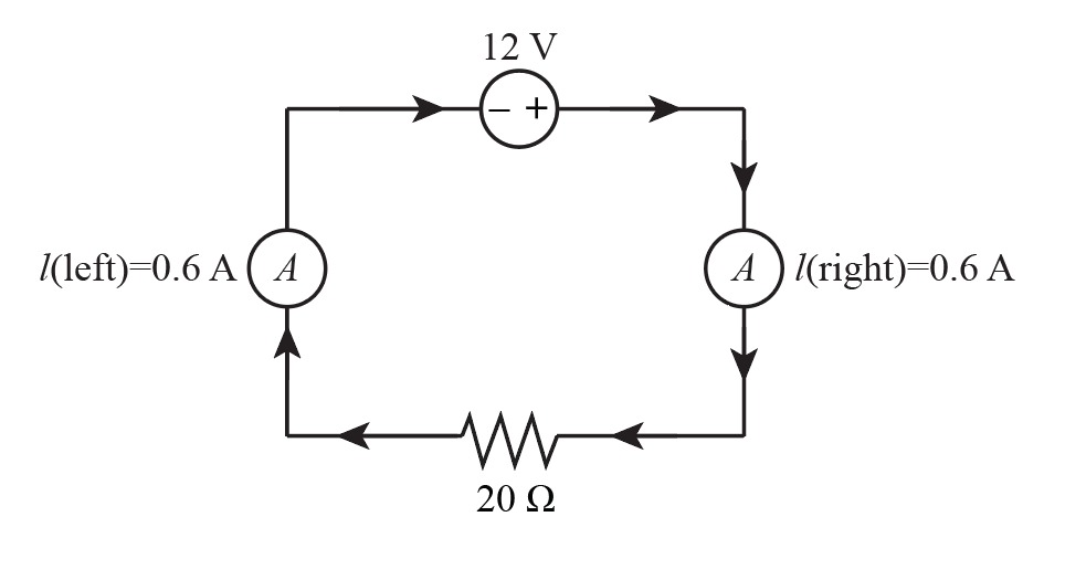
Set the battery voltage to 12 V, and the value of the resistor to 20 ohms. Measure current on the left side of the resistor and on the right side of the resistor in the circuit. Using Ohm's law, calculate the expected current flow. Compare measured and calculated values.


KVL and KCL
KVL stands for Kirchhoff voltage law. KVL states that the total voltage drops around the loop in any closed electric circuit is equal to the sum of total voltage drop in the same closed loop.
Sign Convention
Science and technology incorporate some ideas and techniques of their own to understand a system skilfully and easily. These techniques are called conventions. For example: Sign conventions of mirrors are used to understand the phenomenon of reflection and refraction in an easier way.
Set the battery voltage to 12 V, and the value of the resistor to 20 ohms. Measure current on the left side of the resistor and on the right side of the resistor in the circuit. Using Ohm's law, calculate the expected current flow. Compare measured and calculated values.

Given data:
The voltage,
The resistance,
The circuit diagram is shown below,

Step by step
Solved in 2 steps with 1 images


