S 0/1 A on for the D input of state b A function for the output bit Z. 00 1/1 10 1/0 0/1 0/0 1/0 01 0/0 11 1/1 fallor
S 0/1 A on for the D input of state b A function for the output bit Z. 00 1/1 10 1/0 0/1 0/0 1/0 01 0/0 11 1/1 fallor

Chapter22: Sequence Control
Section: Chapter Questions
Problem 6SQ: Draw a symbol for a solid-state logic element AND.

Related questions

Question

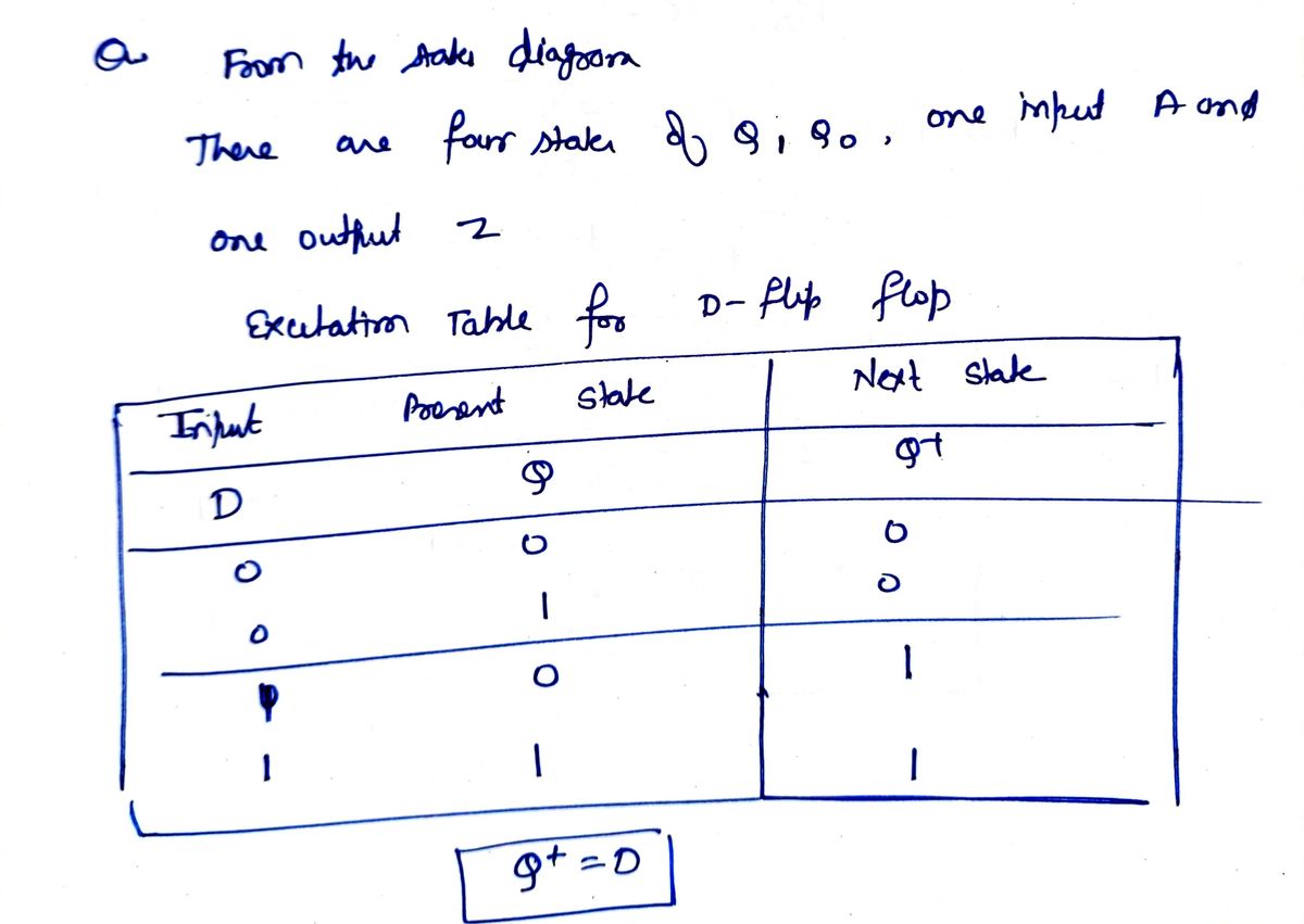
Transcribed Image Text:Implement the following finite state machine using D flip-flops to store the state bits \( Q_1Q_0 \). Express your answer using three Boolean functions in sum-of-products form (call the input bit A):
- A function for the D input of state bit \( Q_1 \).
- A function for the D input of state bit \( Q_0 \).
- A function for the output bit \( Z \).

Transcribed Image Text:The image displays a state diagram for a finite state machine with four states represented as circles labeled "00," "01," "10," and "11." Arrows indicate state transitions, with labels in the format "input/output."
- **State 00**:
- Transition to 01 with input/output 0/0.
- Transition to 10 with input/output 1/1.
- **State 01**:
- Self-loop with input/output 1/1.
- Transition to 11 with input/output 0/0.
- **State 10**:
- Self-loop with input/output 0/1.
- Transition to 00 with input/output 1/0.
- **State 11**:
- Transition to 10 with input/output 0/1.
- Transition to 01 with input/output 1/0.
The starting state is indicated by an 'S' pointing to state 00. This diagram is useful for understanding sequential logic and state transitions in digital design.
Expert Solution
Step 1

Step by step
Solved in 3 steps with 3 images

Knowledge Booster


Learn more about
Need a deep-dive on the concept behind this application? Look no further. Learn more about this topic, electrical-engineering and related others by exploring similar questions and additional content below.Recommended textbooks for you