Review The simply-supported beam is built-up from three boards by nailing them together as shown. The wood has an allowable shear stress of Tallow = 1.5 MPa, and an allowable bending stress of oallow = 9 MPa. The nails are spaced at s = 77 mm, and each has a shear strength of 1.5 kN. (Eigure 1) Part A Determine the maximum allowable force P that can be applied to the beam. Express your answer to three significant figures and include the appropriate units. HÀ ? P= 8.9 kN Submit Previous Answers Request Answer X Incorrect; Try Again; 3 attempts remaining Provide Feedback Next > Figure < 1 of 1> 1 m I m 100 mm 25 mm 25 mm 200 mm 25 mm
Review The simply-supported beam is built-up from three boards by nailing them together as shown. The wood has an allowable shear stress of Tallow = 1.5 MPa, and an allowable bending stress of oallow = 9 MPa. The nails are spaced at s = 77 mm, and each has a shear strength of 1.5 kN. (Eigure 1) Part A Determine the maximum allowable force P that can be applied to the beam. Express your answer to three significant figures and include the appropriate units. HÀ ? P= 8.9 kN Submit Previous Answers Request Answer X Incorrect; Try Again; 3 attempts remaining Provide Feedback Next > Figure < 1 of 1> 1 m I m 100 mm 25 mm 25 mm 200 mm 25 mm

Elements Of Electromagnetics
7th Edition
ISBN:9780190698614
Author:Sadiku, Matthew N. O.
Publisher:Sadiku, Matthew N. O.
ChapterMA: Math Assessment
Section: Chapter Questions
Problem 1.1MA

Related questions
Question

Transcribed Image Text:The problem involves determining the maximum allowable force \( P \) that can be applied to a simply-supported beam composed of three boards nailed together. Here are the details provided:
### Beam Specifications:
- **Shear Stress**: The wood has an allowable shear stress of \( \tau_{\text{allow}} = 1.5 \, \text{MPa} \).
- **Bending Stress**: The allowable bending stress is \( \sigma_{\text{allow}} = 9 \, \text{MPa} \).
- **Nails**:
- Spacing: \( s = 77 \, \text{mm} \).
- Shear Strength: \( 1.5 \, \text{kN} \).
### Task:
Calculate the maximum force, \( P \), applying the above constraints, and express your answer to three significant figures including the units.
### User Input:
- The user attempted to input \( P = 8.9 \, \text{kN} \) and received feedback indicating the answer is incorrect with three attempts remaining.
### Beam Diagram Description:
The diagram shows:
- The beam is supported at points \( A \) and \( B \), with point \( P \) applied at the center of the span.
- Total span of the beam is \( 2 \, \text{m} \) (1 m from support \( A \) to \( P \) and 1 m from \( P \) to support \( B \)).
- Cross-sectional view displays three layers:
- Top and bottom layers are \( 100 \, \text{mm} \) wide and \( 25 \, \text{mm} \) thick.
- Middle layer is \( 200 \, \text{mm} \) wide and \( 25 \, \text{mm} \) thick.
### Interaction:
- Users can submit answers, request answers, or provide feedback.
- The interface confirms submissions and tracks attempts remaining.
Expert Solution
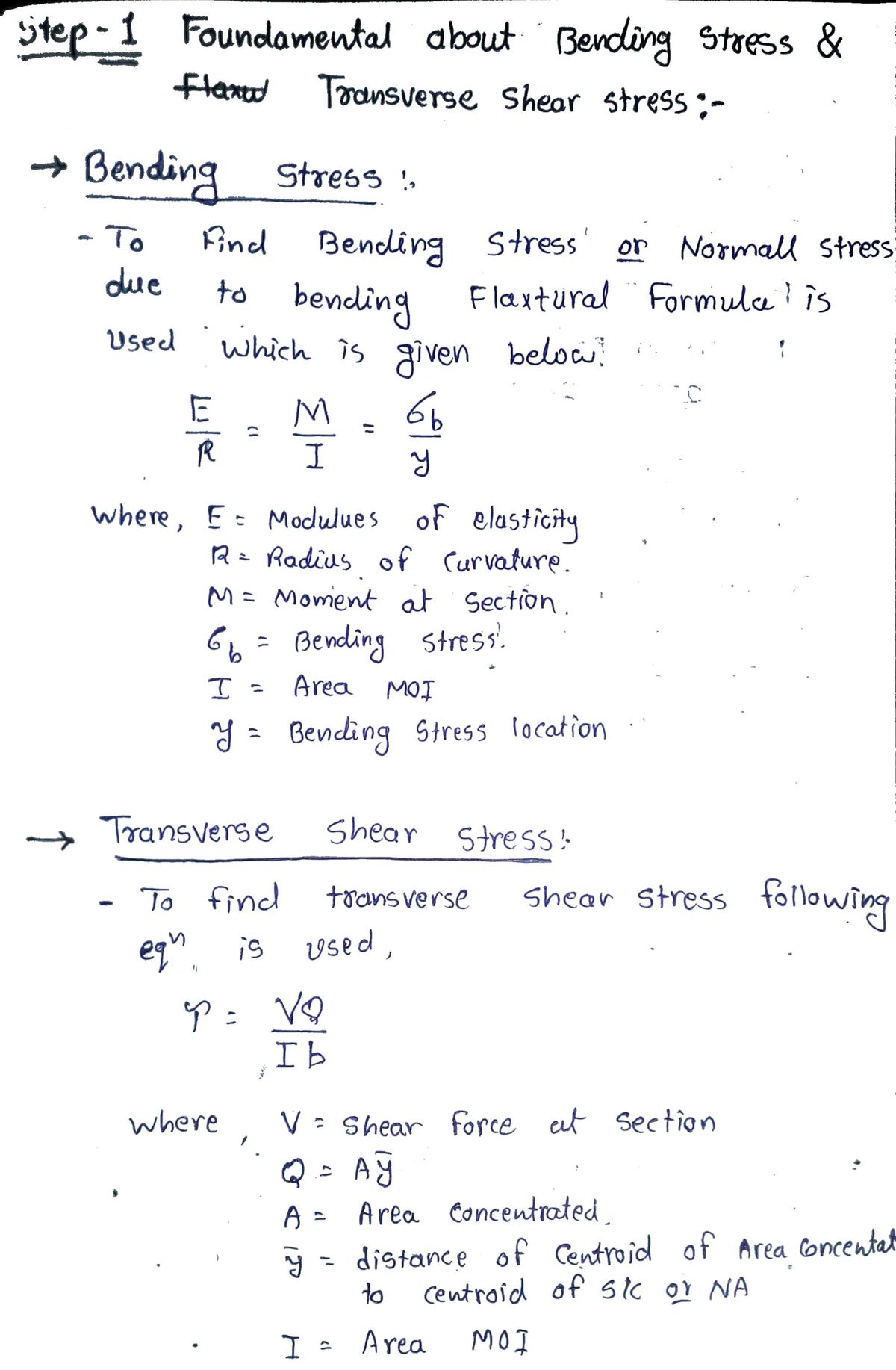
Step 1 Foundamental about Bending Stress and Transverse Shear Stress Formula

Step by step
Solved in 5 steps with 5 images

Recommended textbooks for you
Elements Of Electromagnetics
Mechanical Engineering
ISBN:
9780190698614
Author:
Sadiku, Matthew N. O.
Publisher:
Oxford University Press

Mechanics of Materials (10th Edition)
Mechanical Engineering
ISBN:
9780134319650
Author:
Russell C. Hibbeler
Publisher:
PEARSON

Thermodynamics: An Engineering Approach
Mechanical Engineering
ISBN:
9781259822674
Author:
Yunus A. Cengel Dr., Michael A. Boles
Publisher:
McGraw-Hill Education
Elements Of Electromagnetics
Mechanical Engineering
ISBN:
9780190698614
Author:
Sadiku, Matthew N. O.
Publisher:
Oxford University Press
Mechanics of Materials (10th Edition)
Mechanical Engineering
ISBN:
9780134319650
Author:
Russell C. Hibbeler
Publisher:
PEARSON
Thermodynamics: An Engineering Approach
Mechanical Engineering
ISBN:
9781259822674
Author:
Yunus A. Cengel Dr., Michael A. Boles
Publisher:
McGraw-Hill Education

Control Systems Engineering
Mechanical Engineering
ISBN:
9781118170519
Author:
Norman S. Nise
Publisher:
WILEY

Mechanics of Materials (MindTap Course List)
Mechanical Engineering
ISBN:
9781337093347
Author:
Barry J. Goodno, James M. Gere
Publisher:
Cengage Learning

Engineering Mechanics: Statics
Mechanical Engineering
ISBN:
9781118807330
Author:
James L. Meriam, L. G. Kraige, J. N. Bolton
Publisher:
WILEY