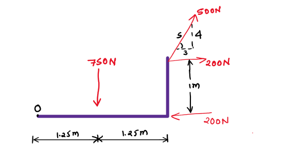
Replace the force and couple moment system acting on the system by a single resultant force and specify its location along the horizontal beam measured from point O. Be specific as to where the resultant force is pointing (i.e. provide an angle and quadrant).
Replace the force and couple moment system acting on the system by a single resultant force and specify its location along the horizontal beam measured from point O. Be specific as to where the resultant force is pointing (i.e. provide an angle and quadrant).
Elements Of Electromagnetics
7th Edition
ISBN:9780190698614
Author:Sadiku, Matthew N. O.
Publisher:Sadiku, Matthew N. O.
ChapterMA: Math Assessment
Section: Chapter Questions
Problem 1.1MA
Related questions
Question
Replace the force and couple moment system acting on the system by a single resultant force and specify its location along the horizontal beam measured from point O. Be specific as to where the resultant force is pointing (i.e. provide an angle and quadrant).

Transcribed Image Text:## Text Transcription for Educational Reference
The problem outlined involves determining the system acting on a beam by a single resultant force.
1. Horizontal Beam System:
- Measured from point O.
- Considering the angle and quadrant of the resultant force.
### Diagram Overview
A diagram depicts a horizontal structure with various applied forces:
- Point O is marked on the far left where the beam is attached to some support.
- A 750 N force is acting vertically downward at a distance of 1.25 m from point O.
- To the right, a 200 N horizontal force is applied 1 meter from the joint.
- Another 200 N force is horizontally applied at the end of the 1.25 m section.
- A 500 N force is applied diagonally upwards, with a slope ratio of 5:4.
### Annotations and Calculations
The calculation appears to solve for the resultant force’s angle and position:
- Possibly annotated with trigonometric calculations.
- The equation in the handwritten section may be solving for rotational effects (moment) around point O or determining the resultant vector using the given slope (e.g., 5/4 for the diagonal force).
The handwritten notes include:
- A breakdown of line equations suggesting angles and moments.
- The sum of forces and moments possibly leading to 494 N as derived from these equations.
- Labels suggesting quadrant IV, which could indicate the final angle of the resultant force.
This text and analysis are recommended for students studying vector forces and moments in physics or engineering courses.
Expert Solution
Step 1: Introduce to the given data
Considering The free-body diagram
We need to Replace
The force and couple moment system acting on the system by a single resultant force
Trending now
This is a popular solution!
Step by step
Solved in 4 steps with 14 images

Knowledge Booster
Learn more about
Need a deep-dive on the concept behind this application? Look no further. Learn more about this topic, mechanical-engineering and related others by exploring similar questions and additional content below.Recommended textbooks for you

Elements Of Electromagnetics
Mechanical Engineering
ISBN:
9780190698614
Author:
Sadiku, Matthew N. O.
Publisher:
Oxford University Press

Mechanics of Materials (10th Edition)
Mechanical Engineering
ISBN:
9780134319650
Author:
Russell C. Hibbeler
Publisher:
PEARSON

Thermodynamics: An Engineering Approach
Mechanical Engineering
ISBN:
9781259822674
Author:
Yunus A. Cengel Dr., Michael A. Boles
Publisher:
McGraw-Hill Education

Elements Of Electromagnetics
Mechanical Engineering
ISBN:
9780190698614
Author:
Sadiku, Matthew N. O.
Publisher:
Oxford University Press

Mechanics of Materials (10th Edition)
Mechanical Engineering
ISBN:
9780134319650
Author:
Russell C. Hibbeler
Publisher:
PEARSON

Thermodynamics: An Engineering Approach
Mechanical Engineering
ISBN:
9781259822674
Author:
Yunus A. Cengel Dr., Michael A. Boles
Publisher:
McGraw-Hill Education

Control Systems Engineering
Mechanical Engineering
ISBN:
9781118170519
Author:
Norman S. Nise
Publisher:
WILEY

Mechanics of Materials (MindTap Course List)
Mechanical Engineering
ISBN:
9781337093347
Author:
Barry J. Goodno, James M. Gere
Publisher:
Cengage Learning

Engineering Mechanics: Statics
Mechanical Engineering
ISBN:
9781118807330
Author:
James L. Meriam, L. G. Kraige, J. N. Bolton
Publisher:
WILEY