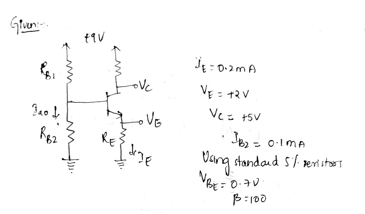
Q3) Design the circuit shown in Fig. 3 to obtain I = 0.2 mA, V₂ = +2V, and Vc=+5V. Design for Iz = 0.1 mA. Use standard 5% resistors. The transistor has Vsr=0.7V and ³ = 100. +9V Figure 3 ove
Q3) Design the circuit shown in Fig. 3 to obtain I = 0.2 mA, V₂ = +2V, and Vc=+5V. Design for Iz = 0.1 mA. Use standard 5% resistors. The transistor has Vsr=0.7V and ³ = 100. +9V Figure 3 ove
Introductory Circuit Analysis (13th Edition)
13th Edition
ISBN:9780133923605
Author:Robert L. Boylestad
Publisher:Robert L. Boylestad
Chapter1: Introduction
Section: Chapter Questions
Problem 1P: Visit your local library (at school or home) and describe the extent to which it provides literature...
Related questions
Question

Transcribed Image Text:Q3) Design the circuit shown in Fig. 3 to obtain = 0.2 mA, Vz= +2V, and Vc = +5V. Design
for Isz = 0.1 mA. Use standard 5% resistors. The transistor has VBE = 0.7V and B = 100.
Table J.1 Standard Resistance Values
5% Resistor Values (km2)
10
11
12
13
15
16
18
20
22
24
27
30
33
36
39
43
47
51
56
62
68
75
82
91
R
100-174
100
102
105
107
110
113
115
118
121
124
127
130
133
137
140
143
147
150
154
158
162
165
169
174
+9V
Figure 3
1% Resistor Values (k)
178-309
316-549
178
316
182
187
191
196
200
205
210
215
221
226
232
237
243
249
255
261
267
ov
274
280
287
294
301
309
324
332
340
348
357
365
374
383
392
402
412
422
432
442
453
464
475
487
499
511
523
536
549
562-976
562
576
590
604
619
634
649
665
681
698
715
732
750
768
787
806
825
845
866
887
909
931
953
976
Expert Solution
Step 1

Step by step
Solved in 3 steps with 3 images

Knowledge Booster
Learn more about
Need a deep-dive on the concept behind this application? Look no further. Learn more about this topic, electrical-engineering and related others by exploring similar questions and additional content below.Recommended textbooks for you

Introductory Circuit Analysis (13th Edition)
Electrical Engineering
ISBN:
9780133923605
Author:
Robert L. Boylestad
Publisher:
PEARSON

Delmar's Standard Textbook Of Electricity
Electrical Engineering
ISBN:
9781337900348
Author:
Stephen L. Herman
Publisher:
Cengage Learning

Programmable Logic Controllers
Electrical Engineering
ISBN:
9780073373843
Author:
Frank D. Petruzella
Publisher:
McGraw-Hill Education

Introductory Circuit Analysis (13th Edition)
Electrical Engineering
ISBN:
9780133923605
Author:
Robert L. Boylestad
Publisher:
PEARSON

Delmar's Standard Textbook Of Electricity
Electrical Engineering
ISBN:
9781337900348
Author:
Stephen L. Herman
Publisher:
Cengage Learning

Programmable Logic Controllers
Electrical Engineering
ISBN:
9780073373843
Author:
Frank D. Petruzella
Publisher:
McGraw-Hill Education

Fundamentals of Electric Circuits
Electrical Engineering
ISBN:
9780078028229
Author:
Charles K Alexander, Matthew Sadiku
Publisher:
McGraw-Hill Education

Electric Circuits. (11th Edition)
Electrical Engineering
ISBN:
9780134746968
Author:
James W. Nilsson, Susan Riedel
Publisher:
PEARSON

Engineering Electromagnetics
Electrical Engineering
ISBN:
9780078028151
Author:
Hayt, William H. (william Hart), Jr, BUCK, John A.
Publisher:
Mcgraw-hill Education,