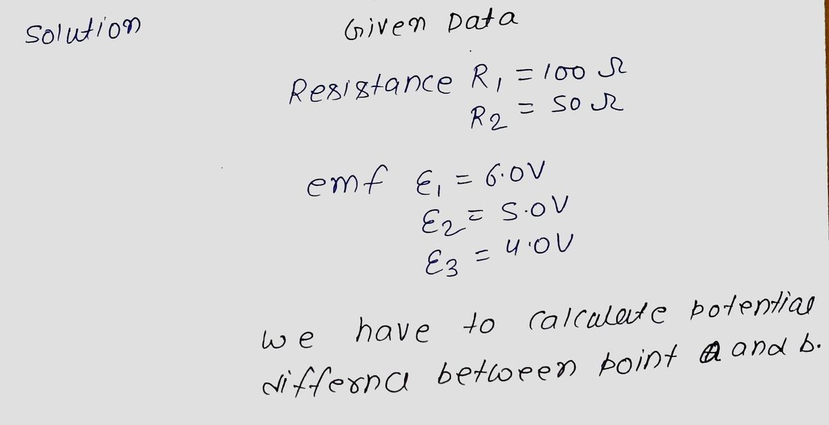
[Q13] The figure shows R₁ = 100 N, R₂ = 50 S, and the ideal batteries (no internal resistance) have emfs of ₁ = 6.0 V, ₂ = 5.0 V, and ɛ3 = 4.0 V. Find the potential difference between points a and b. a E2 R₁ M E₁ Es R₂
[Q13] The figure shows R₁ = 100 N, R₂ = 50 S, and the ideal batteries (no internal resistance) have emfs of ₁ = 6.0 V, ₂ = 5.0 V, and ɛ3 = 4.0 V. Find the potential difference between points a and b. a E2 R₁ M E₁ Es R₂
Related questions
Question

Transcribed Image Text:**Question 13:**
The figure shows a circuit with resistors and batteries:
- Resistor \( R_1 = 100 \, \Omega \)
- Resistor \( R_2 = 50 \, \Omega \)
The circuit includes ideal batteries (no internal resistance) with the following electromotive forces (emfs):
- \( \varepsilon_1 = 6.0 \, \text{V} \)
- \( \varepsilon_2 = 5.0 \, \text{V} \)
- \( \varepsilon_3 = 4.0 \, \text{V} \)
**Task:**
Find the potential difference between points \( a \) and \( b \).
**Diagram Explanation:**
The circuit diagram includes the following elements:
1. **Batteries and their orientations:**
- \( \varepsilon_1 \) is oriented with the positive terminal on top.
- \( \varepsilon_2 \) and \( \varepsilon_3 \) are oriented in the same way with positive terminals facing the junction between the resistors.
2. **Resistors:**
- \( R_1 \) is connected in series with \( \varepsilon_2 \).
- \( R_2 \) is connected in parallel with the combination of \( R_1 \), \( \varepsilon_2 \), and \( \varepsilon_3 \).
3. **Points of Interest:**
- Point \( a \) is located to the left of the circuit, before any voltage drops.
- Point \( b \) is located to the right of the circuit, after the resistors and batteries.
The task requires calculating the voltage difference (\( V \)) between points \( a \) and \( b \).
Expert Solution
Step 1

Step by step
Solved in 2 steps with 2 images
