Q1. Links BC and De are made of the same material (E = 29x106 psi) %3D and have the same cross sectional area (0.125 in?). If the applied force P at point A is 600 lb. Find the forces in links BC and DE. Bar FA is rigid. must show an appropriated free body diagram. A 4 in. B C 2 in. E DO 2 in. F 4 in. 5 in.
Q1. Links BC and De are made of the same material (E = 29x106 psi) %3D and have the same cross sectional area (0.125 in?). If the applied force P at point A is 600 lb. Find the forces in links BC and DE. Bar FA is rigid. must show an appropriated free body diagram. A 4 in. B C 2 in. E DO 2 in. F 4 in. 5 in.

Elements Of Electromagnetics
7th Edition
ISBN:9780190698614
Author:Sadiku, Matthew N. O.
Publisher:Sadiku, Matthew N. O.
ChapterMA: Math Assessment
Section: Chapter Questions
Problem 1.1MA

Related questions

Question

Transcribed Image Text:**Question 1:**
Links BC and DE are made of the same material (E = 29x10^6 psi) and have the same cross-sectional area (0.125 in²). If the applied force P at point A is 600 lb, find the forces in links BC and DE. Bar FA is rigid.
You must show an appropriate free body diagram.
---
**Diagram Explanation:**
The image shows a mechanical system with several components:
- **Link BC**: A horizontal link extending from wall B to point C.
- **Link DE**: A horizontal link extending from point D to wall E.
- **Bar FA**: A vertical rigid bar connected at point A, experiencing the applied force P in the horizontal direction (rightwards).
- **Point F**: The lower end of bar FA, with connections to link DE and positioned on the ground or base.
- **Pinned Supports**:
- At point C, connecting links BC and DE.
- At point D, connecting link DE to bar FA.
**Dimensions:**
- The vertical section from point F to D is 2 inches, and from D to A is 4 inches.
- The horizontal section from wall B to point C is 4 inches, and from point C to E is 5 inches.
This setup is a typical example of a statically determinate structure used in engineering mechanics to solve for unknown forces in components under load. The problem requires using principles of equilibrium and mechanics of materials to find the forces in the links.
Expert Solution
Step 1
The free-body diagram of the figure is given below:
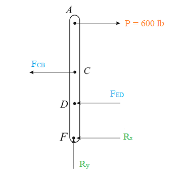
Taking moment about point F :

Step by step
Solved in 4 steps with 2 images

Knowledge Booster


Learn more about
Need a deep-dive on the concept behind this application? Look no further. Learn more about this topic, mechanical-engineering and related others by exploring similar questions and additional content below.Recommended textbooks for you
Elements Of Electromagnetics
Mechanical Engineering
ISBN:
9780190698614
Author:
Sadiku, Matthew N. O.
Publisher:
Oxford University Press

Mechanics of Materials (10th Edition)
Mechanical Engineering
ISBN:
9780134319650
Author:
Russell C. Hibbeler
Publisher:
PEARSON

Thermodynamics: An Engineering Approach
Mechanical Engineering
ISBN:
9781259822674
Author:
Yunus A. Cengel Dr., Michael A. Boles
Publisher:
McGraw-Hill Education
Elements Of Electromagnetics
Mechanical Engineering
ISBN:
9780190698614
Author:
Sadiku, Matthew N. O.
Publisher:
Oxford University Press
Mechanics of Materials (10th Edition)
Mechanical Engineering
ISBN:
9780134319650
Author:
Russell C. Hibbeler
Publisher:
PEARSON
Thermodynamics: An Engineering Approach
Mechanical Engineering
ISBN:
9781259822674
Author:
Yunus A. Cengel Dr., Michael A. Boles
Publisher:
McGraw-Hill Education

Control Systems Engineering
Mechanical Engineering
ISBN:
9781118170519
Author:
Norman S. Nise
Publisher:
WILEY

Mechanics of Materials (MindTap Course List)
Mechanical Engineering
ISBN:
9781337093347
Author:
Barry J. Goodno, James M. Gere
Publisher:
Cengage Learning

Engineering Mechanics: Statics
Mechanical Engineering
ISBN:
9781118807330
Author:
James L. Meriam, L. G. Kraige, J. N. Bolton
Publisher:
WILEY