Q₁ = 20cfs P₁ = 15 psi LFE 36in k P₂² FNA •> 24 in 45 0 = 14.78 Psi
Q₁ = 20cfs P₁ = 15 psi LFE 36in k P₂² FNA •> 24 in 45 0 = 14.78 Psi

Elements Of Electromagnetics
7th Edition
ISBN:9780190698614
Author:Sadiku, Matthew N. O.
Publisher:Sadiku, Matthew N. O.
ChapterMA: Math Assessment
Section: Chapter Questions
Problem 1.1MA

Related questions

Question

Transcribed Image Text:### Diagram: Bent Pipe Flow Analysis
#### Description
This diagram illustrates the flow of fluid through a bent pipe, demonstrating various forces and measurements involved in the system.
#### Details
- **Pipe Geometry**:
- The inlet has a diameter of **36 inches**.
- The outlet has a diameter of **24 inches** and exits at an angle of **45°** to the horizontal.
- **Fluid Flow**:
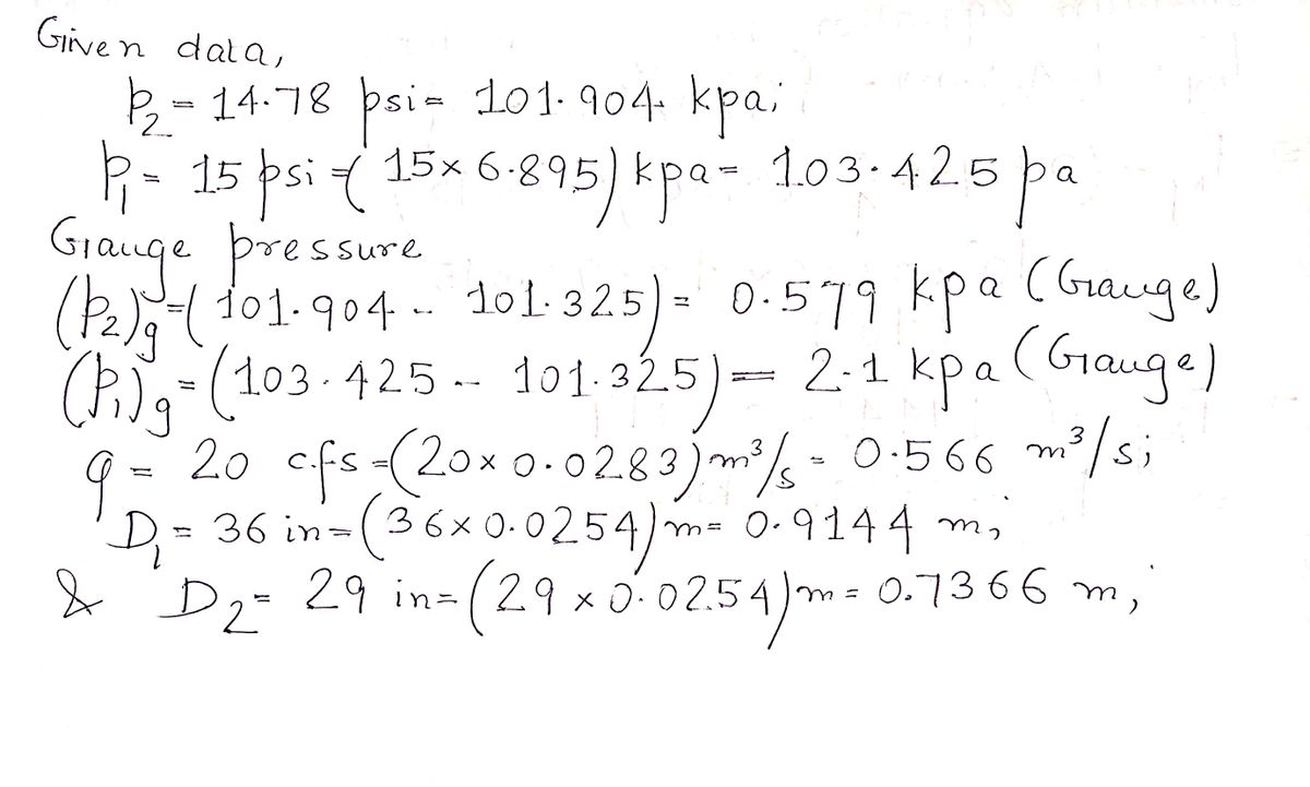
- **Flow Rate (Q₁)**: The fluid enters the pipe at a flow rate of **20 cubic feet per second (cfs)**.
- **Inlet Pressure (P₁)**: The pressure at the inlet is **15 psi**.
- **Outlet Conditions**:
- **Outlet Pressure (P₂)**: The pressure at the outlet is **14.78 psi**.
- **Forces**:
- **F₁**: Represents the force exerted by the fluid at the inlet.
- **F₂**: Represents the force exerted by the fluid at the outlet.
- **Fₙ**: The net force exerted at the bend.
- **Fₙₓ and Fₙᵧ**: Components of the net force in the x and y directions.
- **Coordinate System**:
- The diagram uses a coordinate system with x and y axes to show directionality.
This diagram is used for analyzing fluid dynamics and forces in a bent pipe scenario, common in civil and mechanical engineering applications.
![The image contains mathematical notations and diagrams related to fluid dynamics, specifically addressing forces in a bent pipe. Below is a transcription and explanation suitable for an educational website:
---
### Fluid Dynamics: Calculating Forces in a Bent Pipe
**Given Parameters:**
- **Flow Rate (Q):** 20 cubic feet per second (cfs)
- **Pressure at Point 1 (P₁):** 15 psi
- **Pressure at Point 2 (P₂):** 14.78 psi
**Pipe Dimensions and Angle:**
- **Pipe Length:** 36 inches
- **Angle of Bend:** 45°
- **Section Diameter:** Not specified
**Diagram:**
The diagram illustrates a bend in a pipe with horizontal and vertical components of force. The pipe initially extends straight before making a 45° bend. There are forces denoted as **Fₙₓ** and **Fₙᵧ** acting at the bend, with components aligned to the x-axis and y-axis respectively.
**Objective:**
Neglecting head loss in the bend, calculate the force acting on the bend.
**Force Equations:**
- **x-component of force:**
\[
\rho Q (u₂ - u₁) = \sum E_{\text{ext}, x} = F₁ - F₂ \cos 45° - F_{N,x}
\]
- **y-component of force:**
\[
\rho Q (v₂ - v₁) = \sum E_{\text{ext}, y} = F_{N,y} - F₂ \sin 45°
\]
**Solution Approach:**
To determine the resultant force (**|Fₙ|**) and direction (angle α), solve for both **Fₙₓ** and **Fₙᵧ**:
- **Resultant Force:**
\[
|F_N| = \sqrt{F_{N,x}^2 + F_{N,y}^2}
\]
- **Angle (α):**
\[
\alpha = \arctan \left(\frac{F_{N,y}}{F_{N,x}}\right)
\]
These equations and diagram details provide the basis for calculating the forces exerted on a pipe bend, incorporating principles of fluid mechanics and vector components.](/v2/_next/image?url=https%3A%2F%2Fcontent.bartleby.com%2Fqna-images%2Fquestion%2F4ce8b870-93ef-497a-8c2a-bbbd1041dd5b%2F078c3d52-80e7-42bd-80a0-32f7747f2c9f%2Fe5gmdrm_processed.jpeg&w=3840&q=75)
Transcribed Image Text:The image contains mathematical notations and diagrams related to fluid dynamics, specifically addressing forces in a bent pipe. Below is a transcription and explanation suitable for an educational website:
---
### Fluid Dynamics: Calculating Forces in a Bent Pipe
**Given Parameters:**
- **Flow Rate (Q):** 20 cubic feet per second (cfs)
- **Pressure at Point 1 (P₁):** 15 psi
- **Pressure at Point 2 (P₂):** 14.78 psi
**Pipe Dimensions and Angle:**
- **Pipe Length:** 36 inches
- **Angle of Bend:** 45°
- **Section Diameter:** Not specified
**Diagram:**
The diagram illustrates a bend in a pipe with horizontal and vertical components of force. The pipe initially extends straight before making a 45° bend. There are forces denoted as **Fₙₓ** and **Fₙᵧ** acting at the bend, with components aligned to the x-axis and y-axis respectively.
**Objective:**
Neglecting head loss in the bend, calculate the force acting on the bend.
**Force Equations:**
- **x-component of force:**
\[
\rho Q (u₂ - u₁) = \sum E_{\text{ext}, x} = F₁ - F₂ \cos 45° - F_{N,x}
\]
- **y-component of force:**
\[
\rho Q (v₂ - v₁) = \sum E_{\text{ext}, y} = F_{N,y} - F₂ \sin 45°
\]
**Solution Approach:**
To determine the resultant force (**|Fₙ|**) and direction (angle α), solve for both **Fₙₓ** and **Fₙᵧ**:
- **Resultant Force:**
\[
|F_N| = \sqrt{F_{N,x}^2 + F_{N,y}^2}
\]
- **Angle (α):**
\[
\alpha = \arctan \left(\frac{F_{N,y}}{F_{N,x}}\right)
\]
These equations and diagram details provide the basis for calculating the forces exerted on a pipe bend, incorporating principles of fluid mechanics and vector components.
Expert Solution
Step 1: Determining the given data

Trending now
This is a popular solution!

Step by step
Solved in 5 steps with 5 images

Knowledge Booster


Learn more about
Need a deep-dive on the concept behind this application? Look no further. Learn more about this topic, mechanical-engineering and related others by exploring similar questions and additional content below.Recommended textbooks for you
Elements Of Electromagnetics
Mechanical Engineering
ISBN:
9780190698614
Author:
Sadiku, Matthew N. O.
Publisher:
Oxford University Press

Mechanics of Materials (10th Edition)
Mechanical Engineering
ISBN:
9780134319650
Author:
Russell C. Hibbeler
Publisher:
PEARSON

Thermodynamics: An Engineering Approach
Mechanical Engineering
ISBN:
9781259822674
Author:
Yunus A. Cengel Dr., Michael A. Boles
Publisher:
McGraw-Hill Education
Elements Of Electromagnetics
Mechanical Engineering
ISBN:
9780190698614
Author:
Sadiku, Matthew N. O.
Publisher:
Oxford University Press
Mechanics of Materials (10th Edition)
Mechanical Engineering
ISBN:
9780134319650
Author:
Russell C. Hibbeler
Publisher:
PEARSON
Thermodynamics: An Engineering Approach
Mechanical Engineering
ISBN:
9781259822674
Author:
Yunus A. Cengel Dr., Michael A. Boles
Publisher:
McGraw-Hill Education

Control Systems Engineering
Mechanical Engineering
ISBN:
9781118170519
Author:
Norman S. Nise
Publisher:
WILEY

Mechanics of Materials (MindTap Course List)
Mechanical Engineering
ISBN:
9781337093347
Author:
Barry J. Goodno, James M. Gere
Publisher:
Cengage Learning

Engineering Mechanics: Statics
Mechanical Engineering
ISBN:
9781118807330
Author:
James L. Meriam, L. G. Kraige, J. N. Bolton
Publisher:
WILEY