path function of 0.1? 8. Figure 9.30 shows an electrical circuit and its block diagram representation. What is the overall transfer function of the system? 9. Use block simplification to arrive at the overall transfer function of the systems shown in Figure 9.31. 10. What is the overall transfer function for the systems shown in Figure 9.32? 11. A closed-loop negative feedback system to be used for controlling the position
path function of 0.1? 8. Figure 9.30 shows an electrical circuit and its block diagram representation. What is the overall transfer function of the system? 9. Use block simplification to arrive at the overall transfer function of the systems shown in Figure 9.31. 10. What is the overall transfer function for the systems shown in Figure 9.32? 11. A closed-loop negative feedback system to be used for controlling the position

Introductory Circuit Analysis (13th Edition)
13th Edition
ISBN:9780133923605
Author:Robert L. Boylestad
Publisher:Robert L. Boylestad
Chapter1: Introduction
Section: Chapter Questions
Problem 1P: Visit your local library (at school or home) and describe the extent to which it provides literature...

Related questions
Question
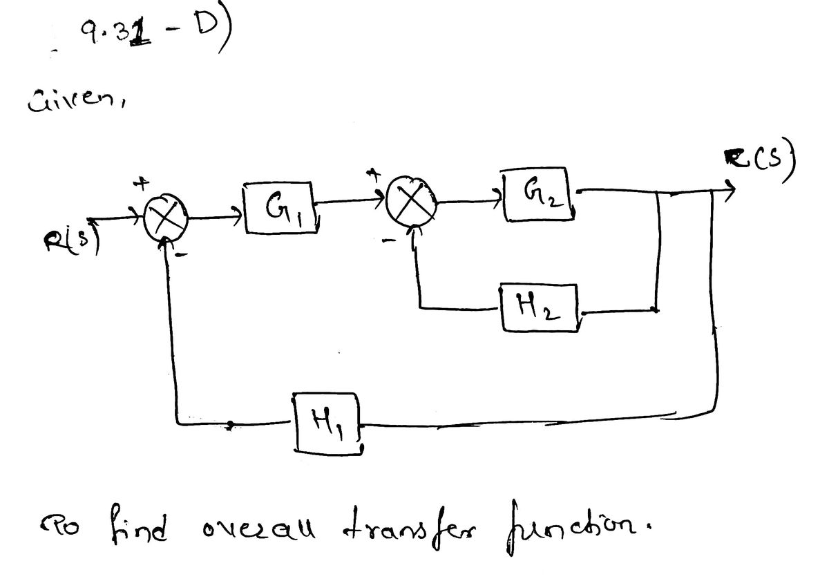
Number 9 letter D

Transcribed Image Text:AXIX | b | me ★ ¹|wGS S0
m/Downloads/instrumentation-and-control-systems-3nbsped-0128234717-9780128234716_compress.pdf
+
2
CD Page view A Read aloud
transfer function of 2/(s + 1) and a feedback path transfer function of 0.1?
8. Figure 9.30 shows an electrical circuit and its block diagram representation. What is the overall transfer
function of the system?
FIGURE 9.30 Problem 8.
O
Input
V
9. Use block simplification to arrive at the overall transfer function of the systems shown in Figure 9.31.
10. What is the overall transfer function for the systems shown in Figure 9.32?
O
R
11. A closed-loop negative feedback system to be used for controlling the position of a load has a differential
amplifier with transfer function K₁ operating a motor with transfer function 1/(sL+ R). The output of the..
motor operates a gear system with gear ratio N and this, in turn, operates a screw with transfer function 1/s
to give the resulting displacement. The position sensor is a potentiometer and this gives a feedback voltage
related to the position of the load by the transfer function K₂. Derive the transfer function for the system as a
whole, relating the input voltage to the system to the displacement output.
12. A closed-loop negative feedback system for the control of the height of liquid in a tank by pumping liquid
from a reservoir tank can be considered to be a system with a differential amplifier having a transfer function
of 5, its output operating a pump with a transfer function 5/(s + 1). The coupled system of tanks has a
transfer function, relating height in the tank to the output from the pump, of 3/(s + 1)(s + 2). The feedback
sensor of the height level in the tank has a transfer function of 0.1. Determine the overall transfer function of
the system, relating the input voltage signal to the system to the height of liquid in the tank.
13. For the control system shown in Figure 9.33, determine the output Y(s) in terms of the inputs X₁(s) and X₂(s).
14. For the control system shown in Figure 9.34, determine the output Y(s) in terms of the inputs X₁ (s) and X₂(s).
C
www
Output
VC
V (s)
Add textDraw
PROBLEMS
PUB
R
1
Cs
INSTRUMENTATION AND CONTROL SYSTEMS
Gix b ▸
V
Vc(s)
Highlight
225
=1218
V
Erase

Transcribed Image Text:+
nloads/instrumentation-and-control-systems-3nbsped-0128234717-9780128234716_compress.pdf
A Read aloud T Add text
?
8
▬
▬▬
FIGURE 9.30 Problem 8.
(A)
(C)
me WGS IS OG b
Gix ▸
CD Page view
(A)
FIGURE 9.31 Problem 9.
Search
O
Input
V
G₁ - G₂
G₁
G3
2
R
G₂
C
G₂
Output
VC
V (s)
INSTRUMENTATION AND CONTROL SYSTEMS
➜
PROBLEMS
(B)
(D)
R
(B)
G₁
G₁
H₂
1
Cs
S+2
Draw
Vc(s)
G₂ →
G3
G₂
H₂
K
J 2 ×
V
►
Highlight
225
W
V
BGX
12181-
Erase |
Expert Solution
Step 1

Step by step
Solved in 3 steps with 3 images

Knowledge Booster


Learn more about
Need a deep-dive on the concept behind this application? Look no further. Learn more about this topic, electrical-engineering and related others by exploring similar questions and additional content below.Recommended textbooks for you
Introductory Circuit Analysis (13th Edition)
Electrical Engineering
ISBN:
9780133923605
Author:
Robert L. Boylestad
Publisher:
PEARSON

Delmar's Standard Textbook Of Electricity
Electrical Engineering
ISBN:
9781337900348
Author:
Stephen L. Herman
Publisher:
Cengage Learning

Programmable Logic Controllers
Electrical Engineering
ISBN:
9780073373843
Author:
Frank D. Petruzella
Publisher:
McGraw-Hill Education
Introductory Circuit Analysis (13th Edition)
Electrical Engineering
ISBN:
9780133923605
Author:
Robert L. Boylestad
Publisher:
PEARSON
Delmar's Standard Textbook Of Electricity
Electrical Engineering
ISBN:
9781337900348
Author:
Stephen L. Herman
Publisher:
Cengage Learning
Programmable Logic Controllers
Electrical Engineering
ISBN:
9780073373843
Author:
Frank D. Petruzella
Publisher:
McGraw-Hill Education

Fundamentals of Electric Circuits
Electrical Engineering
ISBN:
9780078028229
Author:
Charles K Alexander, Matthew Sadiku
Publisher:
McGraw-Hill Education

Electric Circuits. (11th Edition)
Electrical Engineering
ISBN:
9780134746968
Author:
James W. Nilsson, Susan Riedel
Publisher:
PEARSON

Engineering Electromagnetics
Electrical Engineering
ISBN:
9780078028151
Author:
Hayt, William H. (william Hart), Jr, BUCK, John A.
Publisher:
Mcgraw-hill Education,