PaoBLEM# 4:24 I Compose the truth table and K-map for a full-adder. Name the inputs A (addend #1), B (addend #2), and Cin (carry in). The outputs are Cout (carry out) and S (sum). Design the simplest implementation possible. The full-adder is the workhorse of most arithmetic circuits. It is imperative to have the most efficient full-adder possible You will need to examine several different
PaoBLEM# 4:24 I Compose the truth table and K-map for a full-adder. Name the inputs A (addend #1), B (addend #2), and Cin (carry in). The outputs are Cout (carry out) and S (sum). Design the simplest implementation possible. The full-adder is the workhorse of most arithmetic circuits. It is imperative to have the most efficient full-adder possible You will need to examine several different

Introductory Circuit Analysis (13th Edition)
13th Edition
ISBN:9780133923605
Author:Robert L. Boylestad
Publisher:Robert L. Boylestad
Chapter1: Introduction
Section: Chapter Questions
Problem 1P: Visit your local library (at school or home) and describe the extent to which it provides literature...

Related questions
Question
100%

Transcribed Image Text:PaoBLEM# 4:24 I Compose the truth table and K-map for a full-adder.
Name the inputs A (addend #1), B (addend #2), and Cin (carry in).
The outputs are Cout (carry out) and S (sum). Design the simplest
implementation possible. The full-adder is the workhorse of most
arithmetic circuits. It is imperative to have the most efficient
full-adder possible. You will need to examine several different
approaches, and design the simplest implementation possible. What
is your circuit's cost and delay?
Expert Solution
Step 1
FULL ADDER:
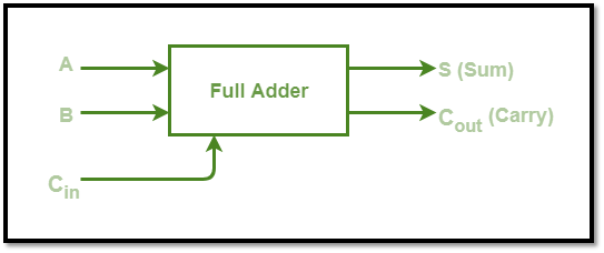
1. Full Adder is a logic circuit that combines two or more logic gates.
2. It is used to add two single-bit integers that have a carry.
3. As a result, the complete adder can do three-bit addition.
4. A full adder has three inputs and two outputs (sum and carry).
The block-diagram of a fill-adder is shown below:

Step by step
Solved in 4 steps with 5 images

Recommended textbooks for you
Introductory Circuit Analysis (13th Edition)
Electrical Engineering
ISBN:
9780133923605
Author:
Robert L. Boylestad
Publisher:
PEARSON

Delmar's Standard Textbook Of Electricity
Electrical Engineering
ISBN:
9781337900348
Author:
Stephen L. Herman
Publisher:
Cengage Learning

Programmable Logic Controllers
Electrical Engineering
ISBN:
9780073373843
Author:
Frank D. Petruzella
Publisher:
McGraw-Hill Education
Introductory Circuit Analysis (13th Edition)
Electrical Engineering
ISBN:
9780133923605
Author:
Robert L. Boylestad
Publisher:
PEARSON
Delmar's Standard Textbook Of Electricity
Electrical Engineering
ISBN:
9781337900348
Author:
Stephen L. Herman
Publisher:
Cengage Learning
Programmable Logic Controllers
Electrical Engineering
ISBN:
9780073373843
Author:
Frank D. Petruzella
Publisher:
McGraw-Hill Education

Fundamentals of Electric Circuits
Electrical Engineering
ISBN:
9780078028229
Author:
Charles K Alexander, Matthew Sadiku
Publisher:
McGraw-Hill Education

Electric Circuits. (11th Edition)
Electrical Engineering
ISBN:
9780134746968
Author:
James W. Nilsson, Susan Riedel
Publisher:
PEARSON

Engineering Electromagnetics
Electrical Engineering
ISBN:
9780078028151
Author:
Hayt, William H. (william Hart), Jr, BUCK, John A.
Publisher:
Mcgraw-hill Education,