Ob Oc n the following circuit junctions diagrammed below, which combination of current directions is not possible? The red arrows in each diagram represent the current directions. T ㅜ T O d.
Ob Oc n the following circuit junctions diagrammed below, which combination of current directions is not possible? The red arrows in each diagram represent the current directions. T ㅜ T O d.

Introductory Circuit Analysis (13th Edition)
13th Edition
ISBN:9780133923605
Author:Robert L. Boylestad
Publisher:Robert L. Boylestad
Chapter1: Introduction
Section: Chapter Questions
Problem 1P: Visit your local library (at school or home) and describe the extent to which it provides literature...

Related questions

Question
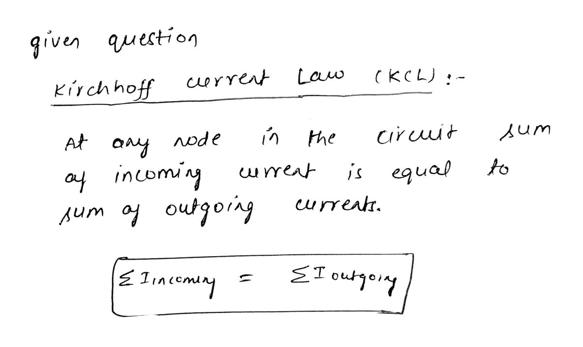
In the following circuit junctions diagrammed below, which combination of current directions is not possible? The red arrows in each diagram represent the current directions.

Transcribed Image Text:In the following circuit junctions diagrammed below, which combination of current directions is not possible? The red arrows in each diagram represent the current directions.
- **Option a**: Incoming current from the top left and right, with outgoing current downwards.
- **Option b**: Incoming current from the left, outgoing current to the right and downwards.
- **Option c**: Incoming current from the left and right, with outgoing current downwards.
- **Option d**: Incoming current from the bottom, with outgoing current left and right.
- **Option e**: Incoming current from the left and downwards, with outgoing current to the right.
In each of these diagrams, the arrows indicate the direction in which electric current is flowing at a junction. The task is to determine which configuration is not possible based on the principle of conservation of charge and current flow in circuits.
Expert Solution
Step 1

Step by step
Solved in 2 steps with 2 images

Knowledge Booster


Learn more about
Need a deep-dive on the concept behind this application? Look no further. Learn more about this topic, electrical-engineering and related others by exploring similar questions and additional content below.Recommended textbooks for you
Introductory Circuit Analysis (13th Edition)
Electrical Engineering
ISBN:
9780133923605
Author:
Robert L. Boylestad
Publisher:
PEARSON

Delmar's Standard Textbook Of Electricity
Electrical Engineering
ISBN:
9781337900348
Author:
Stephen L. Herman
Publisher:
Cengage Learning

Programmable Logic Controllers
Electrical Engineering
ISBN:
9780073373843
Author:
Frank D. Petruzella
Publisher:
McGraw-Hill Education
Introductory Circuit Analysis (13th Edition)
Electrical Engineering
ISBN:
9780133923605
Author:
Robert L. Boylestad
Publisher:
PEARSON
Delmar's Standard Textbook Of Electricity
Electrical Engineering
ISBN:
9781337900348
Author:
Stephen L. Herman
Publisher:
Cengage Learning
Programmable Logic Controllers
Electrical Engineering
ISBN:
9780073373843
Author:
Frank D. Petruzella
Publisher:
McGraw-Hill Education

Fundamentals of Electric Circuits
Electrical Engineering
ISBN:
9780078028229
Author:
Charles K Alexander, Matthew Sadiku
Publisher:
McGraw-Hill Education

Electric Circuits. (11th Edition)
Electrical Engineering
ISBN:
9780134746968
Author:
James W. Nilsson, Susan Riedel
Publisher:
PEARSON

Engineering Electromagnetics
Electrical Engineering
ISBN:
9780078028151
Author:
Hayt, William H. (william Hart), Jr, BUCK, John A.
Publisher:
Mcgraw-hill Education,