length of o2a (link 2) is 5 cm (link 3) is 4 cm (link 3) and the length of the bo4 (link 4) is 5.5 cm (5 in.). At the a point working the p = 50 Newton style with the sustric orientation of the horizontal line is 20⁰, look for styles that are going on and torque on link
length of o2a (link 2) is 5 cm (link 3) is 4 cm (link 3) and the length of the bo4 (link 4) is 5.5 cm (5 in.). At the a point working the p = 50 Newton style with the sustric orientation of the horizontal line is 20⁰, look for styles that are going on and torque on link

Elements Of Electromagnetics
7th Edition
ISBN:9780190698614
Author:Sadiku, Matthew N. O.
Publisher:Sadiku, Matthew N. O.
ChapterMA: Math Assessment
Section: Chapter Questions
Problem 1.1MA

Related questions
Question
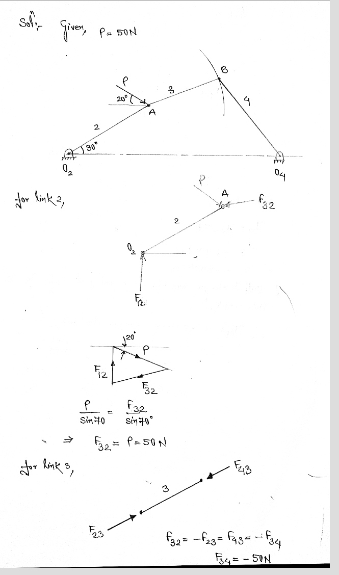
A four-part mechanism like this one, if it is known the length of o2a (link 2) is 5 cm (link 3) is 4 cm (link 3) and the length of the bo4 (link 4) is 5.5 cm (5 in.). At the a point working the p = 50 Newton style with the sustric orientation of the horizontal line is 20⁰, look for styles that are going on and torque on link 4.

Transcribed Image Text:The image features a diagram of a mechanical structure with several labeled points, lines, and angles. Here's a detailed description:
- **Points:**
- O2: A fixed point at the left base of the structure, where a rod or member originates.
- A: A joint connected to two members, acting as a pivotal point.
- B: Another joint located farther along the structure from point A.
- O4: A fixed point at the right base of the structure, where another rod or member originates.
- **Members:**
- Member O2A is labeled with the length "2" and is inclined at an angle of 30° from the horizontal baseline.
- Member AB is labeled with the length "3."
- Member BO4 is labeled with the length "4."
- **Force:**
- There is a force denoted as "P" applied at point A. This force forms a 20° angle with the horizontal line extending from point A.
The structure appears to be a pinned or trussed framework with forces and angles indicating static or dynamic equilibrium analysis. The lengths and angles are essential for calculations related to mechanical or structural engineering, such as determining tension, compression, or the resultant force on different members of the structure.
Expert Solution
Step 1

Step by step
Solved in 2 steps with 2 images

Recommended textbooks for you
Elements Of Electromagnetics
Mechanical Engineering
ISBN:
9780190698614
Author:
Sadiku, Matthew N. O.
Publisher:
Oxford University Press

Mechanics of Materials (10th Edition)
Mechanical Engineering
ISBN:
9780134319650
Author:
Russell C. Hibbeler
Publisher:
PEARSON

Thermodynamics: An Engineering Approach
Mechanical Engineering
ISBN:
9781259822674
Author:
Yunus A. Cengel Dr., Michael A. Boles
Publisher:
McGraw-Hill Education
Elements Of Electromagnetics
Mechanical Engineering
ISBN:
9780190698614
Author:
Sadiku, Matthew N. O.
Publisher:
Oxford University Press
Mechanics of Materials (10th Edition)
Mechanical Engineering
ISBN:
9780134319650
Author:
Russell C. Hibbeler
Publisher:
PEARSON
Thermodynamics: An Engineering Approach
Mechanical Engineering
ISBN:
9781259822674
Author:
Yunus A. Cengel Dr., Michael A. Boles
Publisher:
McGraw-Hill Education

Control Systems Engineering
Mechanical Engineering
ISBN:
9781118170519
Author:
Norman S. Nise
Publisher:
WILEY

Mechanics of Materials (MindTap Course List)
Mechanical Engineering
ISBN:
9781337093347
Author:
Barry J. Goodno, James M. Gere
Publisher:
Cengage Learning

Engineering Mechanics: Statics
Mechanical Engineering
ISBN:
9781118807330
Author:
James L. Meriam, L. G. Kraige, J. N. Bolton
Publisher:
WILEY