Learning Goal: The rectangular cross section ABCD shown below has a circular cutout of diameter d = 50.0 mm through its center. The member is subjected to two externally applied moments M₁ = 6.0 kN m and M₂ =17.0 kN-m at angles 0₁ = 35.0 degrees from the y axis in the yz plane and 0 = 25.0 degrees from the z axis in the yz plane, respectively. The rectangular cross section has a height of h = 290.0 mm and a width of w=125.0 mm. Y C M, 8 2 M₂ Part A - Free-body diagram of the resolved components of the moments The two externally applied moments can be resolved into their respective y and 2 components. Determine the moments in each principal direction, My and M,, and draw the corresponding free-body diagram Draw the vectors My and M, that represent the total y and z components of the two externally applied moments. Assume all angles are measured in degrees.
Learning Goal: The rectangular cross section ABCD shown below has a circular cutout of diameter d = 50.0 mm through its center. The member is subjected to two externally applied moments M₁ = 6.0 kN m and M₂ =17.0 kN-m at angles 0₁ = 35.0 degrees from the y axis in the yz plane and 0 = 25.0 degrees from the z axis in the yz plane, respectively. The rectangular cross section has a height of h = 290.0 mm and a width of w=125.0 mm. Y C M, 8 2 M₂ Part A - Free-body diagram of the resolved components of the moments The two externally applied moments can be resolved into their respective y and 2 components. Determine the moments in each principal direction, My and M,, and draw the corresponding free-body diagram Draw the vectors My and M, that represent the total y and z components of the two externally applied moments. Assume all angles are measured in degrees.

Elements Of Electromagnetics
7th Edition
ISBN:9780190698614
Author:Sadiku, Matthew N. O.
Publisher:Sadiku, Matthew N. O.
ChapterMA: Math Assessment
Section: Chapter Questions
Problem 1.1MA

Related questions

Question

Transcribed Image Text:Learning Goal:
The rectangular cross section ABCD shown below has a circular cutout of diameter d = 50.0 mm through its center. The member is subjected to two externally applied moments M₁ = 6.0 kNm and M₂ = 17.0 kN-m at angles 0₁ = 35.0
degrees from the y axis in the yz plane and 02 = 25.0 degrees from the z axis in the yz plane, respectively. The rectangular cross section has a height of h = 290.0 mm and a width of w = 125.0 mm
▼
2722
M₁ 8₁
2
d
B
78₂
W
2
Part A - Free-body diagram of the resolved components of the moments
The two externally applied moments can be resolved into their respective y and z components. Determine the moments in each principal direction, My and M₂, and draw the corresponding free-body diagram.
Draw the vectors My and M₂ that represent the total y and z components of the two externally applied moments. Assume all angles are measured in degrees.

Transcribed Image Text:Part C - Neutral-axis angle due to externally applied moments
4
The neutral-axis angle of the cross section being analyzed is the axis along which there is a zero stress
value. Determine the neutral-axis angle, a, due to the externally applied moments as measured
counterclockwise from the positive z axis in the yz plane.
Express your answer to three significant figures and include the appropriate units.
►View Available Hint(s)
a =
Submit
HÅ
Value
Units
BICEI
?
Part D- Absolute maximum stress in cross section ABCD
Determine the absolute maximum stress, max. in cross section ABCD due to the two externally applied
moments.
Express the answer to three significant figures and include the appropriate units.
+
Expert Solution
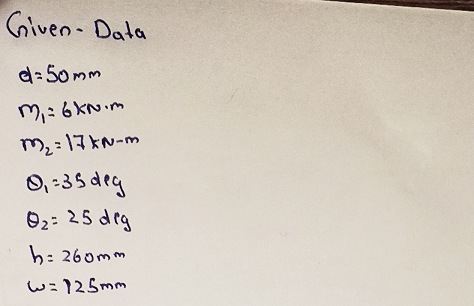
Step 1: Given data
List of all the given data in this problem is shown below.

Step by step
Solved in 4 steps with 4 images

Knowledge Booster


Learn more about
Need a deep-dive on the concept behind this application? Look no further. Learn more about this topic, mechanical-engineering and related others by exploring similar questions and additional content below.Recommended textbooks for you
Elements Of Electromagnetics
Mechanical Engineering
ISBN:
9780190698614
Author:
Sadiku, Matthew N. O.
Publisher:
Oxford University Press

Mechanics of Materials (10th Edition)
Mechanical Engineering
ISBN:
9780134319650
Author:
Russell C. Hibbeler
Publisher:
PEARSON

Thermodynamics: An Engineering Approach
Mechanical Engineering
ISBN:
9781259822674
Author:
Yunus A. Cengel Dr., Michael A. Boles
Publisher:
McGraw-Hill Education
Elements Of Electromagnetics
Mechanical Engineering
ISBN:
9780190698614
Author:
Sadiku, Matthew N. O.
Publisher:
Oxford University Press
Mechanics of Materials (10th Edition)
Mechanical Engineering
ISBN:
9780134319650
Author:
Russell C. Hibbeler
Publisher:
PEARSON
Thermodynamics: An Engineering Approach
Mechanical Engineering
ISBN:
9781259822674
Author:
Yunus A. Cengel Dr., Michael A. Boles
Publisher:
McGraw-Hill Education

Control Systems Engineering
Mechanical Engineering
ISBN:
9781118170519
Author:
Norman S. Nise
Publisher:
WILEY

Mechanics of Materials (MindTap Course List)
Mechanical Engineering
ISBN:
9781337093347
Author:
Barry J. Goodno, James M. Gere
Publisher:
Cengage Learning

Engineering Mechanics: Statics
Mechanical Engineering
ISBN:
9781118807330
Author:
James L. Meriam, L. G. Kraige, J. N. Bolton
Publisher:
WILEY