If the EMF is 12 V, then determine the following. (a) What is the equivalent resistance of the circuit in the diagram? (b) What is the voltage across the 4.0 Ω resistor? (c) What is the current in the 3.0 Ω resistor? (d) Show your steps in the process of reducing the circuit.
If the EMF is 12 V, then determine the following. (a) What is the equivalent resistance of the circuit in the diagram? (b) What is the voltage across the 4.0 Ω resistor? (c) What is the current in the 3.0 Ω resistor? (d) Show your steps in the process of reducing the circuit.

College Physics
11th Edition
ISBN:9781305952300
Author:Raymond A. Serway, Chris Vuille
Publisher:Raymond A. Serway, Chris Vuille
Chapter18: Direct-Current Circuits
Section: Chapter Questions
Problem 10CQ: An uncharged series RC circuit is to be connected across a battery. For each of the following...

Related questions
Question
If the EMF is 12 V, then determine the following. (a) What is the equivalent resistance of the circuit in the diagram? (b) What is the voltage across the 4.0 Ω resistor? (c) What is the current in the 3.0 Ω resistor? (d) Show your steps in the process of reducing the circuit.

Transcribed Image Text:The image depicts an electrical circuit featuring resistors and a voltage source. The configuration and values of the resistors are as follows:
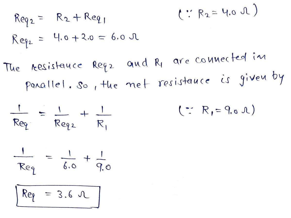
1. **Resistor R1**: This resistor is labeled as 9.0 ohms (Ω). It is positioned in series with the voltage source (depicted as ε).
2. **Resistor R2**: This resistor has a value of 4.0 ohms (Ω) and is placed in series with the voltage source and R1.
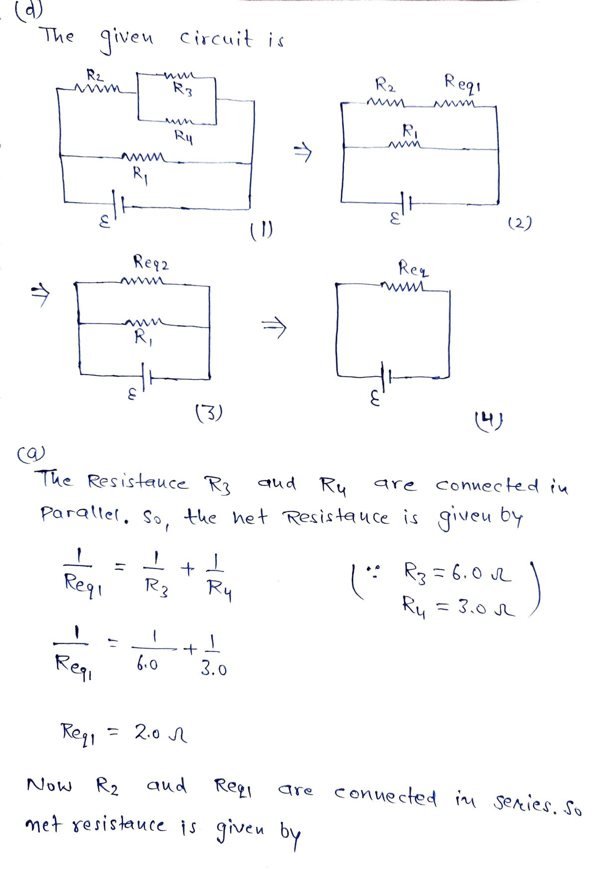
3. **Resistor R3**: This resistor is valued at 6.0 ohms (Ω) and is connected in parallel with R4.
4. **Resistor R4**: This resistor shows a value of 3.0 ohms (Ω) and forms a parallel connection with R3.
The circuit starts with the voltage source, followed by R1. After R1, the circuit splits, with one path containing R2 and the other branching off to the parallel combination of R3 and R4. The parallel arrangement of R3 and R4 provides an alternative path for the current between the series components R1 and R2.
This type of circuit configuration is useful for understanding concepts such as series and parallel resistances, voltage division, current paths, and how these elements interact within an electrical circuit.
Expert Solution
Step 1

Step by step
Solved in 3 steps with 4 images

Knowledge Booster


Learn more about
Need a deep-dive on the concept behind this application? Look no further. Learn more about this topic, physics and related others by exploring similar questions and additional content below.Recommended textbooks for you
College Physics
Physics
ISBN:
9781305952300
Author:
Raymond A. Serway, Chris Vuille
Publisher:
Cengage Learning

College Physics
Physics
ISBN:
9781285737027
Author:
Raymond A. Serway, Chris Vuille
Publisher:
Cengage Learning

Principles of Physics: A Calculus-Based Text
Physics
ISBN:
9781133104261
Author:
Raymond A. Serway, John W. Jewett
Publisher:
Cengage Learning
College Physics
Physics
ISBN:
9781305952300
Author:
Raymond A. Serway, Chris Vuille
Publisher:
Cengage Learning
College Physics
Physics
ISBN:
9781285737027
Author:
Raymond A. Serway, Chris Vuille
Publisher:
Cengage Learning
Principles of Physics: A Calculus-Based Text
Physics
ISBN:
9781133104261
Author:
Raymond A. Serway, John W. Jewett
Publisher:
Cengage Learning

Physics for Scientists and Engineers
Physics
ISBN:
9781337553278
Author:
Raymond A. Serway, John W. Jewett
Publisher:
Cengage Learning

Physics for Scientists and Engineers with Modern …
Physics
ISBN:
9781337553292
Author:
Raymond A. Serway, John W. Jewett
Publisher:
Cengage Learning

Physics for Scientists and Engineers, Technology …
Physics
ISBN:
9781305116399
Author:
Raymond A. Serway, John W. Jewett
Publisher:
Cengage Learning