i) R(s)→ 5 G₁ G4 G₂ G₁ G₂ 3 10 -Y(s) Figure 6. Use the block diagram reduction technique to determine the equivalent transfer function I
i) R(s)→ 5 G₁ G4 G₂ G₁ G₂ 3 10 -Y(s) Figure 6. Use the block diagram reduction technique to determine the equivalent transfer function I

Power System Analysis and Design (MindTap Course List)
6th Edition
ISBN:9781305632134
Author:J. Duncan Glover, Thomas Overbye, Mulukutla S. Sarma
Publisher:J. Duncan Glover, Thomas Overbye, Mulukutla S. Sarma
Chapter6: Power Flows
Section: Chapter Questions
Problem 6.22P

Related questions

Question
Please help answer this question.
Please answer in typing format please ASAP for the like please clear the solution

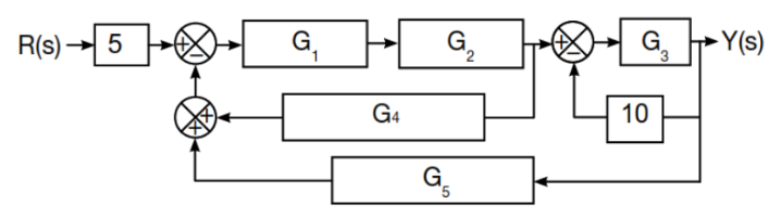
Transcribed Image Text:The provided image displays a complex block diagram, typically used in control systems to represent the flow of signals and operations through various system components.
### Description of the Block Diagram:
1. **Input and Output:**
- The input is labeled as \( R(s) \), and the output is labeled as \( Y(s) \).
2. **Components and Blocks:**
- There are multiple blocks labeled as \( G_1 \), \( G_2 \), \( G_3 \), \( G_4 \), and \( G_5 \). Each of these represents a system with its own transfer function.
- Two constants are given: \( 5 \) and \( 10 \).
3. **Summing Points:**
- There are three summing points (represented by circles with plus and minus signs), which indicate where signals are either added or subtracted.
4. **Signal Flow:**
- The input \( R(s) \) passes through a block with the constant \( 5 \).
- The first summing point subtracts the feedback signal and sends it to \( G_1 \).
- The output of \( G_1 \) flows to \( G_2 \).
- The output of \( G_2 \) moves to the second summing point, which adds the feedback from \( G_4 \) before proceeding to \( G_3 \).
- The output of \( G_3 \) is \( Y(s) \).
- \( G_4 \) receives its input from the output of \( G_2 \).
- \( G_5 \) feeds back into the first summing point.
- The third summing point combines the output of \( G_3 \) with the constant \( 10 \) before feeding back into the loop.
### Instruction:
i) Use the block diagram reduction technique to determine the equivalent transfer function.
This problem requires the application of block diagram reduction techniques to simplify the given diagram and determine the overall transfer function from \( R(s) \) to \( Y(s) \). Standard techniques involve algebraically manipulating the arrangement of blocks and summing points to find an equivalent, simplified transfer function expression.
Expert Solution
Step 1: what is given and what to do:
Given:
Block diagram of a control system,
we need to find the transfer function of the system using block diagram reduction technique.

Step by step
Solved in 3 steps with 8 images

Knowledge Booster


Learn more about
Need a deep-dive on the concept behind this application? Look no further. Learn more about this topic, electrical-engineering and related others by exploring similar questions and additional content below.Recommended textbooks for you
Power System Analysis and Design (MindTap Course …
Electrical Engineering
ISBN:
9781305632134
Author:
J. Duncan Glover, Thomas Overbye, Mulukutla S. Sarma
Publisher:
Cengage Learning

EBK ELECTRICAL WIRING RESIDENTIAL
Electrical Engineering
ISBN:
9781337516549
Author:
Simmons
Publisher:
CENGAGE LEARNING - CONSIGNMENT
Power System Analysis and Design (MindTap Course …
Electrical Engineering
ISBN:
9781305632134
Author:
J. Duncan Glover, Thomas Overbye, Mulukutla S. Sarma
Publisher:
Cengage Learning
EBK ELECTRICAL WIRING RESIDENTIAL
Electrical Engineering
ISBN:
9781337516549
Author:
Simmons
Publisher:
CENGAGE LEARNING - CONSIGNMENT