-> 200 2 800 b Positire Sign Conver Bidh

Chapter2: Loads On Structures
Section: Chapter Questions
Problem 1P

Related questions
Question
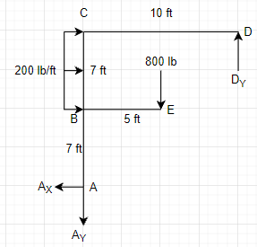
Find all moments in every joint from each member (in lb-ft).

Transcribed Image Text:The image features two diagrams on a grid paper, illustrating a beam structure with applied loads and dimensions. Below is a detailed explanation suitable for an educational website:
---
### Diagram Explanation
#### Diagram 1: Front View of the Beam Structure
- **Points and Labels:**
- The structure includes labeled points: A, B, C, D, and E.
- Arrows indicate forces and moments along specific points.
- **Dimensions:**
- The horizontal dimensions are labeled with an interval of 5 feet between A to B and B to E.
- Vertical distances are indicated as 1 foot and 2 feet from A to B and B to C, respectively.
- **Load Applications:**
- A constant distributed load of 200 pounds per foot (lb/ft) acts vertically downward from point B to point C.
- A concentrated load of 800 pounds acts downward at point E.
#### Diagram 2: Sign Convention and Loading Directions
- **Sign Convention:**
- Illustrations show the positive sign convention for moments and forces, with curved arrows.
- **Loading Directions:**
- The loading directions on this smaller scale diagram use curved arrows at each joint (A, B, C, D, E) to depict the direction of forces and moments in the structure.
#### Additional Notes:
- The diagrams are drawn over a grid to maintain scale and precision, with each square likely representing one square foot.
- The notation `Positive Sign Convention` indicates the standard method for defining directions of forces and moments within beam calculations.
### Applications
These diagrams could be used for explaining basic concepts in structural analysis, including how to interpret loading conditions, analyze beam reactions, and calculate internal forces and moments.
---
This content facilitates understanding of beam loading analysis and sign conventions for students studying civil engineering or structural mechanics.
Expert Solution
Step 1
Given data:

Step by step
Solved in 4 steps with 3 images

Recommended textbooks for you

Structural Analysis (10th Edition)
Civil Engineering
ISBN:
9780134610672
Author:
Russell C. Hibbeler
Publisher:
PEARSON

Principles of Foundation Engineering (MindTap Cou…
Civil Engineering
ISBN:
9781337705028
Author:
Braja M. Das, Nagaratnam Sivakugan
Publisher:
Cengage Learning
Structural Analysis (10th Edition)
Civil Engineering
ISBN:
9780134610672
Author:
Russell C. Hibbeler
Publisher:
PEARSON
Principles of Foundation Engineering (MindTap Cou…
Civil Engineering
ISBN:
9781337705028
Author:
Braja M. Das, Nagaratnam Sivakugan
Publisher:
Cengage Learning

Fundamentals of Structural Analysis
Civil Engineering
ISBN:
9780073398006
Author:
Kenneth M. Leet Emeritus, Chia-Ming Uang, Joel Lanning
Publisher:
McGraw-Hill Education


Traffic and Highway Engineering
Civil Engineering
ISBN:
9781305156241
Author:
Garber, Nicholas J.
Publisher:
Cengage Learning