For a hydroelectric plant, a hydraulic turbine-generator is installed at the site below the free surface. The turbine drives a generator for electricity. The elevation difference between the two free surfaces is h=20m. The power input from the fluid to the turbine is is W = 100kW. The shaft power fluid output from the turbine is W = 80kW. sh (2)Calculate the mass flow rate m of the fluid.
For a hydroelectric plant, a hydraulic turbine-generator is installed at the site below the free surface. The turbine drives a generator for electricity. The elevation difference between the two free surfaces is h=20m. The power input from the fluid to the turbine is is W = 100kW. The shaft power fluid output from the turbine is W = 80kW. sh (2)Calculate the mass flow rate m of the fluid.

Elements Of Electromagnetics
7th Edition
ISBN:9780190698614
Author:Sadiku, Matthew N. O.
Publisher:Sadiku, Matthew N. O.
ChapterMA: Math Assessment
Section: Chapter Questions
Problem 1.1MA

Related questions

Question

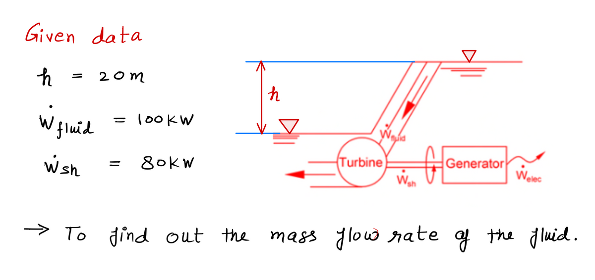
Transcribed Image Text:For a hydroelectric plant, a hydraulic turbine-generator is installed at the site below the free surface. The turbine drives a generator for electricity. The elevation difference between the two free surfaces is \( h = 20 \, \text{m} \). The power input from the fluid to the turbine is \( W_{\text{fluid}} = 100 \, \text{kW} \). The shaft power output from the turbine is \( W_{\text{sh}} = 80 \, \text{kW} \).
**(2) Calculate the mass flow rate \( \dot{m} \) of the fluid.**
__________
- A. 5.10 kg/s
- B. 0.510 kg/s
- C. 10.2 kg/s
- D. 5.1 kg/s
**Diagram Explanation:**
The diagram illustrates the operation of a hydroelectric plant consisting of a turbine and a generator.
- The fluid enters the turbine, imparting power input represented by \( W_{\text{fluid}} \).
- The turbine converts this fluid power into mechanical power (shaft power) denoted by \( W_{\text{sh}} \), which is transferred to the generator.
- The generator then converts the mechanical shaft power into electrical power output represented by \( W_{\text{elec}} \).
The diagram also shows the direction of fluid flow and the conversion of energy from fluid to electrical form.
Expert Solution
Step 1

Step by step
Solved in 2 steps with 2 images

Knowledge Booster


Learn more about
Need a deep-dive on the concept behind this application? Look no further. Learn more about this topic, mechanical-engineering and related others by exploring similar questions and additional content below.Recommended textbooks for you
Elements Of Electromagnetics
Mechanical Engineering
ISBN:
9780190698614
Author:
Sadiku, Matthew N. O.
Publisher:
Oxford University Press

Mechanics of Materials (10th Edition)
Mechanical Engineering
ISBN:
9780134319650
Author:
Russell C. Hibbeler
Publisher:
PEARSON

Thermodynamics: An Engineering Approach
Mechanical Engineering
ISBN:
9781259822674
Author:
Yunus A. Cengel Dr., Michael A. Boles
Publisher:
McGraw-Hill Education
Elements Of Electromagnetics
Mechanical Engineering
ISBN:
9780190698614
Author:
Sadiku, Matthew N. O.
Publisher:
Oxford University Press
Mechanics of Materials (10th Edition)
Mechanical Engineering
ISBN:
9780134319650
Author:
Russell C. Hibbeler
Publisher:
PEARSON
Thermodynamics: An Engineering Approach
Mechanical Engineering
ISBN:
9781259822674
Author:
Yunus A. Cengel Dr., Michael A. Boles
Publisher:
McGraw-Hill Education

Control Systems Engineering
Mechanical Engineering
ISBN:
9781118170519
Author:
Norman S. Nise
Publisher:
WILEY

Mechanics of Materials (MindTap Course List)
Mechanical Engineering
ISBN:
9781337093347
Author:
Barry J. Goodno, James M. Gere
Publisher:
Cengage Learning

Engineering Mechanics: Statics
Mechanical Engineering
ISBN:
9781118807330
Author:
James L. Meriam, L. G. Kraige, J. N. Bolton
Publisher:
WILEY