flow through each pipe. Ioss and 15.27 Two reservoirs having a difference of 40 ft in water elevations are connected by a 1.5-mile- long cast-iron pipe of 1 ft diameter. A second pipe 1.5 ft in diameter and one-half mile in length is laid alongside the first one for the last half mile. How is the discharge affected? 15.28 For the pipe system shown in Fig. P15.28, determine the rate of flow. Disregard the minor losses. Figure P15.28
flow through each pipe. Ioss and 15.27 Two reservoirs having a difference of 40 ft in water elevations are connected by a 1.5-mile- long cast-iron pipe of 1 ft diameter. A second pipe 1.5 ft in diameter and one-half mile in length is laid alongside the first one for the last half mile. How is the discharge affected? 15.28 For the pipe system shown in Fig. P15.28, determine the rate of flow. Disregard the minor losses. Figure P15.28

Chapter2: Loads On Structures
Section: Chapter Questions
Problem 1P

Related questions
Question
15.27

Transcribed Image Text:15.26 A flow of 1 m/s is divided into three parallel cast-iron pipes of diameters 500, 250, and
400 mm and lengths 400 m, 100 m, and 250 m, respectively. Determine the head loss and
flow through each pipe.
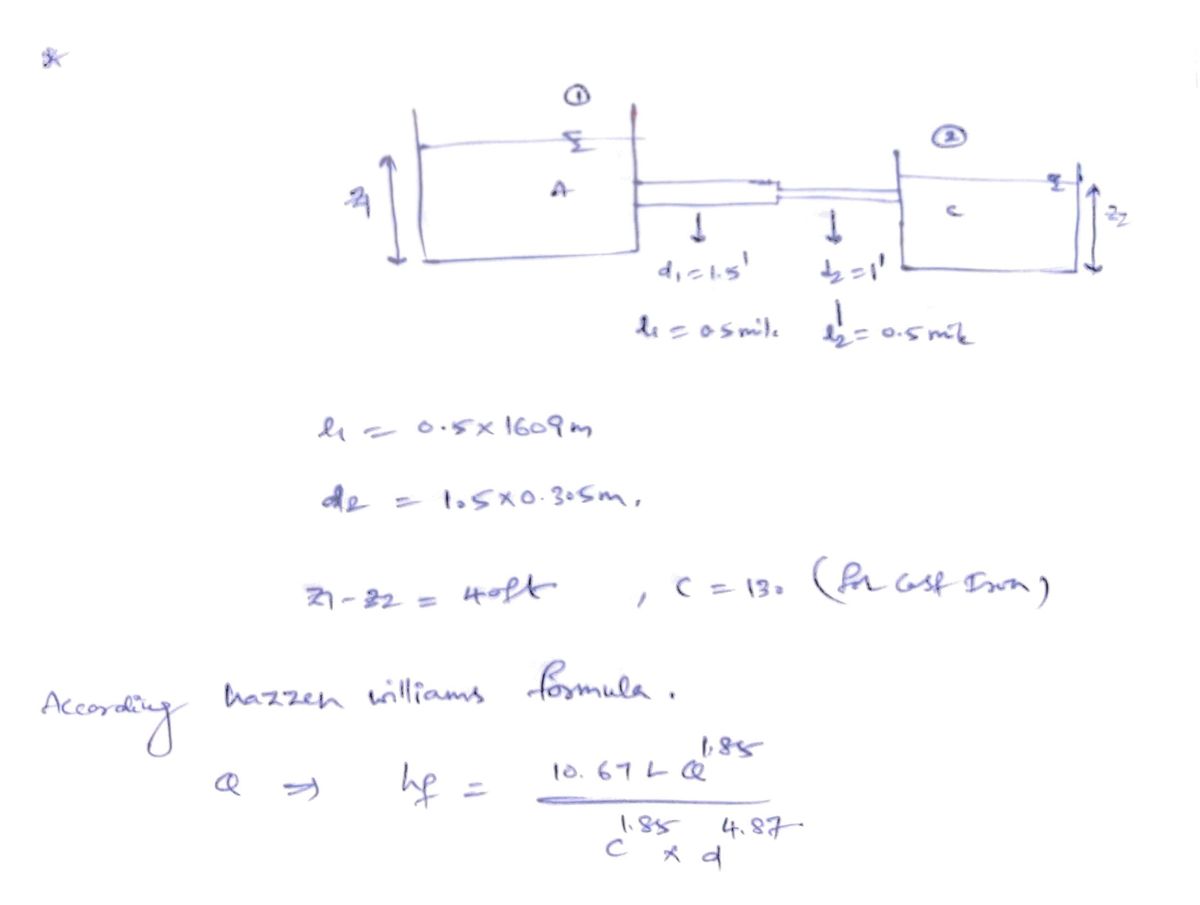
15.27 Two reservoirs having a difference of 40 ft in water elevations are connected by a 1.5-mile-
long cast-iron pipe of 1 ft diameter. A second pipe 1.5 ft in diameter and one-half mile in
length is laid alongside the first one for the last half-mile. How is the discharge affected?
15.28 For the pipe system shown in Fig. P15.28, determine the rate of flow. Disregard the minor
losses.
Figure P15.28
Elevation 1000 ft
6-in. dia, 500 ft
8-in. dia, 1000 ft
12-in. dia, 2000 ft
Elevation 92O ft
4-in, dia, 300 ft
New cast-iron pipe
At point D it is divided into two branches. A 50-cm-diameter, 600-m-long pipe (f=0.024)
connects to reservoir B while a 60-cm-diameter, 1200-m-long pipe (f= 0.02)connects to
reservoir C. The surface elevations at A, B, C, and D are 30 m, 20 m, 10 m, and 25 m,
respectively. Determine the flow in each pipe.
15.29 From reservoir A, water is supplied by a 100-cm-diameter, 3000-m-long pipe (f= 0.015).
Distribution Systems Chapter 15
Expert Solution
Step 1

Trending now
This is a popular solution!

Step by step
Solved in 2 steps with 2 images

Knowledge Booster


Learn more about
Need a deep-dive on the concept behind this application? Look no further. Learn more about this topic, civil-engineering and related others by exploring similar questions and additional content below.Recommended textbooks for you

Structural Analysis (10th Edition)
Civil Engineering
ISBN:
9780134610672
Author:
Russell C. Hibbeler
Publisher:
PEARSON

Principles of Foundation Engineering (MindTap Cou…
Civil Engineering
ISBN:
9781337705028
Author:
Braja M. Das, Nagaratnam Sivakugan
Publisher:
Cengage Learning
Structural Analysis (10th Edition)
Civil Engineering
ISBN:
9780134610672
Author:
Russell C. Hibbeler
Publisher:
PEARSON
Principles of Foundation Engineering (MindTap Cou…
Civil Engineering
ISBN:
9781337705028
Author:
Braja M. Das, Nagaratnam Sivakugan
Publisher:
Cengage Learning

Fundamentals of Structural Analysis
Civil Engineering
ISBN:
9780073398006
Author:
Kenneth M. Leet Emeritus, Chia-Ming Uang, Joel Lanning
Publisher:
McGraw-Hill Education


Traffic and Highway Engineering
Civil Engineering
ISBN:
9781305156241
Author:
Garber, Nicholas J.
Publisher:
Cengage Learning