Find the The ven in and Norton equivalent Circuits tor the terminals a_b. circuit shown at a 15V (+) 4A
Find the The ven in and Norton equivalent Circuits tor the terminals a_b. circuit shown at a 15V (+) 4A

Introductory Circuit Analysis (13th Edition)
13th Edition
ISBN:9780133923605
Author:Robert L. Boylestad
Publisher:Robert L. Boylestad
Chapter1: Introduction
Section: Chapter Questions
Problem 1P: Visit your local library (at school or home) and describe the extent to which it provides literature...

Related questions
Question

Transcribed Image Text:**Objective:**
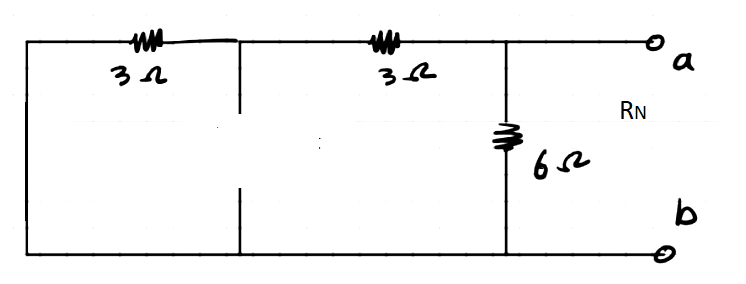
Find the Thevenin and Norton equivalent circuits for the given electrical circuit at terminals a-b.
**Circuit Description:**
The circuit consists of the following components:
- A 15V voltage source on the left side.
- A 3-ohm resistor is connected in series with the 15V voltage source.
- A parallel branch next to the series 3-ohm resistor containing a 4A current source.
- Another 3-ohm resistor in series with the parallel branch.
- A 6-ohm resistor is connected in parallel with the previous series branch.
- Terminals a and b are at the end of the circuit for further analysis.
**Graph/Diagram Explanation:**
The circuit diagram is illustrated on a grid background, showing an arrangement of electrical components and connections. The components are strategically placed to analyze the reduction of the circuit into Thevenin and Norton equivalents. The circuit begins with a voltage source, followed by resistors and a current source arranged to demonstrate various series and parallel connections.
Expert Solution
Step 1
Norton equivalent
Norton resistance
Remove the voltage source by the short-circuit and the current source by the open circuit, the circuit is shown below:
Norton current
The terminal ab is shorted, the circuit is shown below:
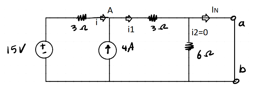
Applying Nodal analysis at node A,
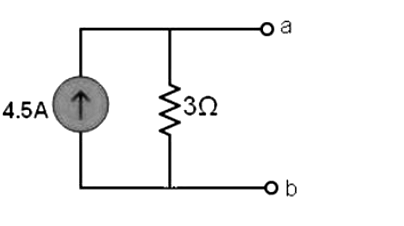
Norton equivalent circuit
The Norton equivalent circuit is shown below:

Step by step
Solved in 2 steps with 6 images

Recommended textbooks for you
Introductory Circuit Analysis (13th Edition)
Electrical Engineering
ISBN:
9780133923605
Author:
Robert L. Boylestad
Publisher:
PEARSON

Delmar's Standard Textbook Of Electricity
Electrical Engineering
ISBN:
9781337900348
Author:
Stephen L. Herman
Publisher:
Cengage Learning

Programmable Logic Controllers
Electrical Engineering
ISBN:
9780073373843
Author:
Frank D. Petruzella
Publisher:
McGraw-Hill Education
Introductory Circuit Analysis (13th Edition)
Electrical Engineering
ISBN:
9780133923605
Author:
Robert L. Boylestad
Publisher:
PEARSON
Delmar's Standard Textbook Of Electricity
Electrical Engineering
ISBN:
9781337900348
Author:
Stephen L. Herman
Publisher:
Cengage Learning
Programmable Logic Controllers
Electrical Engineering
ISBN:
9780073373843
Author:
Frank D. Petruzella
Publisher:
McGraw-Hill Education

Fundamentals of Electric Circuits
Electrical Engineering
ISBN:
9780078028229
Author:
Charles K Alexander, Matthew Sadiku
Publisher:
McGraw-Hill Education

Electric Circuits. (11th Edition)
Electrical Engineering
ISBN:
9780134746968
Author:
James W. Nilsson, Susan Riedel
Publisher:
PEARSON

Engineering Electromagnetics
Electrical Engineering
ISBN:
9780078028151
Author:
Hayt, William H. (william Hart), Jr, BUCK, John A.
Publisher:
Mcgraw-hill Education,