FIND THE PIN REACTION FORCES AT C

Elements Of Electromagnetics
7th Edition
ISBN:9780190698614
Author:Sadiku, Matthew N. O.
Publisher:Sadiku, Matthew N. O.
ChapterMA: Math Assessment
Section: Chapter Questions
Problem 1.1MA

Related questions
Question
FIND THE PIN REACTION FORCES AT C

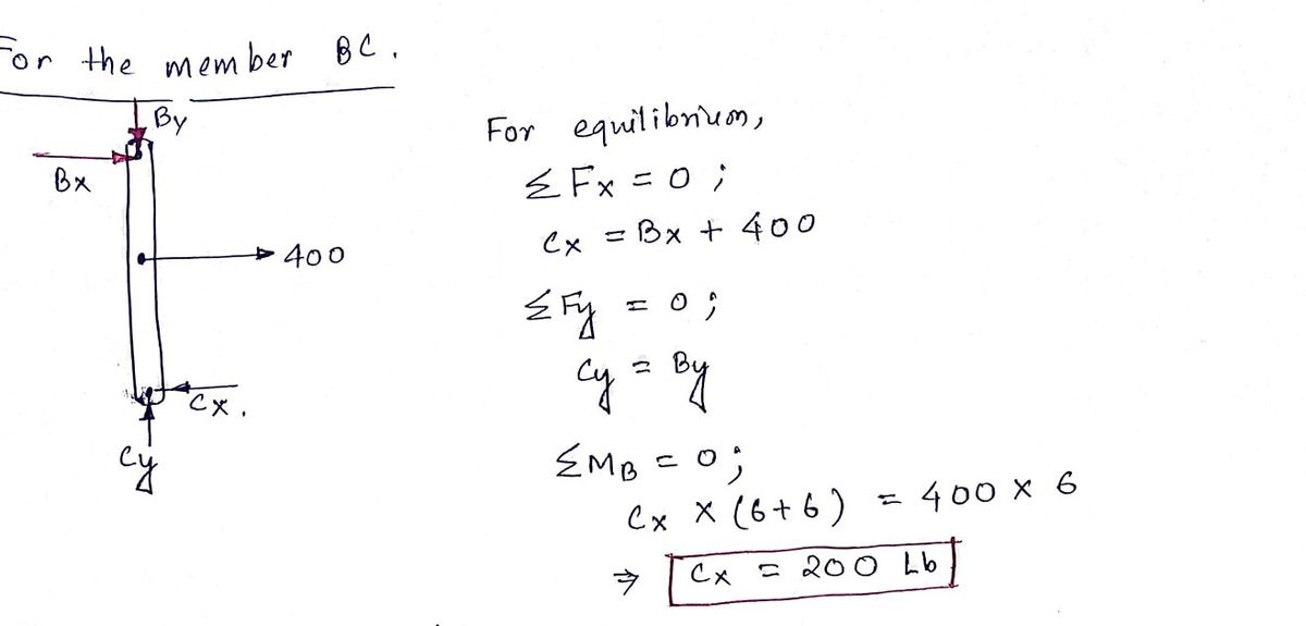
Transcribed Image Text:**Find the Pin Reaction Forces at A, B, & C**
This diagram displays a structural analysis problem focusing on determining the pin reaction forces at points A, B, and C. The layout consists of a framework with specified dimensions and applied forces:
### Structure Dimensions:
- Horizontal spans from left to right are both 8 feet.
- Vertical height at the leftmost vertical support is 6 feet.
- Vertical member from point B to point C is 5 feet in height.
### Applied Forces:
1. A 250-pound force directed downward, acting on a diagonal member, with a 4:3 slope ratio indicated.
2. A horizontal force of 400 pounds applied at point B towards the right.
3. A vertical downward force of 125 pounds at the bottom right end of the diagonal.
### Diagram Explanation:
- Points A and B represent pin connections, depicted as squares with a diagonal cross.
- The structure is composed of two horizontal beams and a vertical member linking A, B, and C.
- Labels indicate distances and force magnitudes for operational clarity.
This setup typically requires equilibrium equations to solve for the reaction forces at the pins, considering both the static equilibrium conditions in both horizontal and vertical directions and moments about the pins.
Expert Solution
Step 1

Step by step
Solved in 2 steps with 2 images

Knowledge Booster


Learn more about
Need a deep-dive on the concept behind this application? Look no further. Learn more about this topic, mechanical-engineering and related others by exploring similar questions and additional content below.Recommended textbooks for you
Elements Of Electromagnetics
Mechanical Engineering
ISBN:
9780190698614
Author:
Sadiku, Matthew N. O.
Publisher:
Oxford University Press

Mechanics of Materials (10th Edition)
Mechanical Engineering
ISBN:
9780134319650
Author:
Russell C. Hibbeler
Publisher:
PEARSON

Thermodynamics: An Engineering Approach
Mechanical Engineering
ISBN:
9781259822674
Author:
Yunus A. Cengel Dr., Michael A. Boles
Publisher:
McGraw-Hill Education
Elements Of Electromagnetics
Mechanical Engineering
ISBN:
9780190698614
Author:
Sadiku, Matthew N. O.
Publisher:
Oxford University Press
Mechanics of Materials (10th Edition)
Mechanical Engineering
ISBN:
9780134319650
Author:
Russell C. Hibbeler
Publisher:
PEARSON
Thermodynamics: An Engineering Approach
Mechanical Engineering
ISBN:
9781259822674
Author:
Yunus A. Cengel Dr., Michael A. Boles
Publisher:
McGraw-Hill Education

Control Systems Engineering
Mechanical Engineering
ISBN:
9781118170519
Author:
Norman S. Nise
Publisher:
WILEY

Mechanics of Materials (MindTap Course List)
Mechanical Engineering
ISBN:
9781337093347
Author:
Barry J. Goodno, James M. Gere
Publisher:
Cengage Learning

Engineering Mechanics: Statics
Mechanical Engineering
ISBN:
9781118807330
Author:
James L. Meriam, L. G. Kraige, J. N. Bolton
Publisher:
WILEY